Cylindricity tolerance controls the roundness and straightness of a cylinder surface, ensuring that the entire cylindrical feature remains within a specified tolerance zone. This geometric tolerance is crucial for parts requiring precise fit, rotation, or sealing, impacting the overall function and performance of mechanical components. Explore the rest of the article to understand how cylindricity tolerances enhance quality and reliability in manufacturing.
Table of Comparison
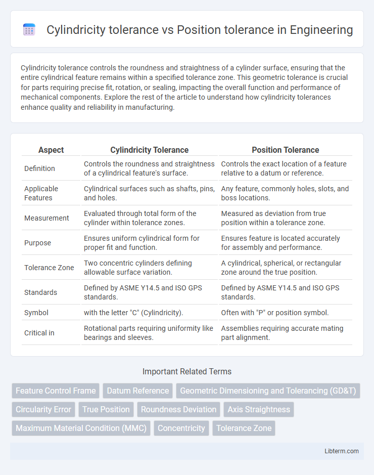
| Aspect | Cylindricity Tolerance | Position Tolerance |
|---|---|---|
| Definition | Controls the roundness and straightness of a cylindrical feature's surface. | Controls the exact location of a feature relative to a datum or reference. |
| Applicable Features | Cylindrical surfaces such as shafts, pins, and holes. | Any feature, commonly holes, slots, and boss locations. |
| Measurement | Evaluated through total form of the cylinder within tolerance zones. | Measured as deviation from true position within a tolerance zone. |
| Purpose | Ensures uniform cylindrical form for proper fit and function. | Ensures feature is located accurately for assembly and performance. |
| Tolerance Zone | Two concentric cylinders defining allowable surface variation. | A cylindrical, spherical, or rectangular zone around the true position. |
| Standards | Defined by ASME Y14.5 and ISO GPS standards. | Defined by ASME Y14.5 and ISO GPS standards. |
| Symbol | with the letter "C" (Cylindricity). | Often with "P" or position symbol. |
| Critical in | Rotational parts requiring uniformity like bearings and sleeves. | Assemblies requiring accurate mating part alignment. |
Introduction to Geometric Dimensioning and Tolerancing (GD&T)
Cylindricity tolerance in Geometric Dimensioning and Tolerancing (GD&T) controls the roundness, straightness, and taper of a cylindrical feature, ensuring uniformity along its entire length. Position tolerance defines the permissible deviation of a feature's center from its true position, critical for accurate assembly and function. Both tolerances are essential for maintaining the geometric integrity of parts, with cylindricity focusing on shape precision and position tolerance emphasizing exact location.
Defining Cylindricity Tolerance
Cylindricity tolerance defines the permissible variation of a cylindrical surface from an ideal cylinder, ensuring uniformity throughout its entire length. It controls the form of the cylinder without reference to any datums, focusing solely on the surface's roundness and straightness in 3D. Compared to position tolerance, which governs the location of features relative to datums, cylindricity tolerance strictly addresses the geometric accuracy of cylindrical shapes.
Understanding Position Tolerance
Position tolerance defines the permissible deviation for the exact location of a feature within a specified tolerance zone, ensuring precise assembly and function in mechanical parts. Unlike cylindricity tolerance, which controls the uniformity of a feature's surface around its axis, position tolerance focuses on the feature's spatial accuracy relative to datums or other features. Understanding position tolerance is crucial for maintaining the functional relationship and proper alignment of components in complex assemblies.
Key Differences Between Cylindricity and Position Tolerances
Cylindricity tolerance controls the overall 3D form of a cylindrical feature, ensuring all surface points lie within a specified zone around the ideal cylinder, emphasizing geometric precision without reference to a datum. Position tolerance defines the exact location, orientation, and sometimes the concentricity of features relative to datums, crucial for assembly and functional relationships in mechanical parts. The key difference lies in cylindricity addressing form control of a single feature, while position tolerance governs the spatial relationship between multiple features or parts.
When to Use Cylindricity Tolerance in Design
Cylindricity tolerance is essential when the entire surface of a cylindrical feature must maintain uniform roundness and straightness to ensure proper sealing, rotation, or fit in assemblies. Use cylindricity tolerance in designs requiring precise shaft or bore control where deviations from a perfect cylinder can impact performance, such as in bearings or hydraulic cylinders. Position tolerance focuses on the exact location of features rather than their uniform shape, making cylindricity preferable for controlling geometric form in cylindrical parts.
When Position Tolerance is Most Suitable
Position tolerance is most suitable when controlling the exact location of a feature relative to a datum or other features, ensuring precise assembly and function in mechanical components. It governs the allowable variation in the center axis of cylindrical features, making it ideal for holes or pins that must fit within a specific positional zone. Unlike cylindricity tolerance, which controls geometric form independently, position tolerance integrates both location and form to meet strict functional alignment requirements.
Inspection Methods for Cylindricity vs Position
Cylindricity tolerance inspection typically involves using roundness measurement instruments such as coordinate measuring machines (CMMs) or cylindrical roundness testers to evaluate the uniformity of a cylinder's surface along its entire length. Position tolerance inspection relies on CMMs equipped with probing systems to verify the exact location, orientation, and axis alignment of features relative to datums or reference points. Both methods require precise data acquisition, but cylindricity emphasizes surface geometry consistency while position tolerance focuses on spatial accuracy and feature location.
Impact on Manufacturing and Cost
Cylindricity tolerance ensures the uniform roundness and straightness of cylindrical features, directly affecting machining precision and increasing manufacturing complexity and cost when tightened. Position tolerance controls the exact location of features relative to datums, impacting assembly accuracy and requiring advanced measuring equipment that can raise inspection and rework expenses. Balancing cylindricity and position tolerances optimizes manufacturing efficiency by reducing unnecessary machining time while maintaining functional fit and performance.
Common Application Examples in Industry
Cylindricity tolerance is commonly applied in manufacturing precision shafts, hydraulic cylinders, and rotary components to ensure uniformity of roundness and straightness along the cylinder's axis. Position tolerance is widely used in the assembly of hole patterns, bolt holes, and locating features to guarantee accurate placement and alignment relative to a datum reference. Both tolerances enhance functionality and interchangeability in automotive, aerospace, and machinery industries by controlling geometric deviations critical for part performance.
Best Practices for Specifying Cylindricity and Position Tolerances
Specify cylindricity tolerance to control the roundness and straightness of a cylindrical feature's surface, ensuring the entire surface lies within two concentric cylinders. Use position tolerance to precisely locate a feature relative to datums, controlling its allowable deviation in multiple axes for assembly accuracy. Best practices include selecting the tightest tolerance that achieves functionality without over-constraining manufacturing, applying geometric dimensioning and tolerancing (GD&T) standards consistently, and referencing appropriate datum features for position tolerances to enhance inspection reliability.
Cylindricity tolerance Infographic