Shear load refers to the force that causes two adjacent parts of a material to slide past each other in opposite directions, often leading to deformation or failure. Understanding shear load is crucial for designing structures and components that can withstand stress without compromising safety or integrity. Discover more about how shear load impacts engineering and how to manage it effectively in the following article.
Table of Comparison
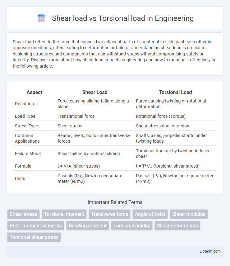
| Aspect | Shear Load | Torsional Load |
|---|---|---|
| Definition | Force causing sliding failure along a plane | Force causing twisting or rotational deformation |
| Load Type | Translational force | Rotational force (Torque) |
| Stress Type | Shear stress | Shear stress due to torsion |
| Common Applications | Beams, rivets, bolts under transverse forces | Shafts, axles, propeller shafts under twisting loads |
| Failure Mode | Shear failure by material sliding | Torsional fracture by twisting-induced shear |
| Formula | t = V/A (shear stress) | t = T*r/J (torsional shear stress) |
| Units | Pascals (Pa), Newton per square meter (N/m2) | Pascals (Pa), Newton per square meter (N/m2) |
Introduction to Shear Load and Torsional Load
Shear load refers to forces applied parallel or tangential to a surface, causing layers of material to slide against each other, commonly seen in beams, bolts, and structural components. Torsional load involves twisting forces that create shear stress over a circular cross-section, typically affecting shafts, rods, and cylindrical objects subjected to torque. Understanding the differences in stress distribution and deformation between shear and torsional loads is critical for designing mechanical parts that withstand operational forces efficiently.
Fundamental Definitions and Concepts
Shear load refers to a force that causes deformation by sliding layers of material parallel to each other, typically measured in units of force per area such as pascals or pounds per square inch. Torsional load involves a twisting force applied around an axis, resulting in shear stress distributed over the cross-sectional area of a shaft or beam, critical in mechanical and structural engineering. Understanding the fundamental differences between shear and torsional loads aids in accurate stress analysis and material selection for components subjected to complex loading conditions.
Key Differences Between Shear and Torsional Loads
Shear load acts parallel to the cross-sectional area of a material, causing internal sliding between layers, while torsional load induces twisting by applying torque around an axis. Shear stresses are uniformly distributed across the affected plane, whereas torsional stresses result in a non-uniform stress distribution that varies radially from the axis of rotation. Different structural components respond uniquely; beams primarily resist shear loads, whereas shafts and rods are predominantly designed to withstand torsional loads.
Sources and Applications of Shear Loads
Shear loads primarily originate from forces applied parallel or tangential to a material's surface, commonly seen in structures like beams, riveted joints, and bolts where sliding failure is critical. These loads are prevalent in applications such as bridges, crane hooks, and mechanical shafts where resisting lateral forces is essential to maintain integrity and prevent material failure. Understanding the sources of shear loads aids in designing components to withstand shear stress, ensuring safety and durability in engineering applications.
Origins and Uses of Torsional Loads
Torsional loads originate from forces causing twisting or rotational stress around an object's axis, commonly seen in shafts, drive trains, and propeller systems. They are crucial in mechanical engineering applications like automotive drive shafts, helicopter rotors, and turbine blades, where torque transmission and resistance to twisting are essential. Understanding torsional loads helps in designing components that withstand rotational forces without failure, ensuring safety and efficiency in machinery and structural systems.
Stress Distribution: Shear vs Torsion
Shear load generates a uniform shear stress distribution across the cross-sectional area of a material, typically resulting in parallel stress planes that resist sliding forces. Torsional load produces a non-uniform shear stress distribution, with maximum shear stresses occurring at the outer surface of circular shafts due to twisting moments. Understanding these distinct stress patterns is crucial for accurate design and failure analysis in mechanical components subjected to combined load conditions.
Material Response Under Shear and Torsion
Materials under shear load experience deformation characterized by parallel internal forces causing layers to slide relative to each other, often resulting in shear strain and potential yielding along the shear plane. In torsional loading, materials are subjected to twisting moments producing shear stresses that vary linearly from the shaft center to the outer surface, with maximum shear stress occurring at the outer radius. The material response under torsion involves elastic shear strain initially followed by plastic deformation if the shear stress exceeds the material's yield strength, influencing the design and failure analysis of shafts and mechanical components.
Failure Modes and Safety Considerations
Shear load failure typically occurs due to material yield or fracture along the plane of applied force, characterized by sudden sliding or buckling in structural components, whereas torsional load failure manifests through twisting deformation leading to shear stresses that cause cracks or fatigue failures in shafts and beams. Safety considerations for shear loads emphasize ensuring adequate cross-sectional area and material shear strength to prevent catastrophic shear rupture, while torsional load safety requires evaluating polar moment of inertia and using materials with high torsional rigidity to avoid excessive angular deformation and fatigue damage. Proper selection of materials, accurate load analysis, and incorporation of safety factors specific to shear and torsional stresses are critical to preventing structural failure and ensuring long-term reliability.
Calculation Methods for Shear and Torsional Loads
Shear load calculations primarily involve determining the shear force acting perpendicular to a material's cross-section using formulas like V = F/A, where V is shear stress, F is the applied force, and A is the area. Torsional load calculations focus on the shear stress caused by twisting moments, using t = T*r/J, where t represents the shear stress, T is the torque, r is the radius, and J is the polar moment of inertia. Both calculations require precise measurement of material properties and geometric parameters to ensure accurate stress analysis for structural design.
Practical Examples and Engineering Implications
Shear load occurs when forces act parallel or tangential to a material's surface, such as in rivets or bolts holding two plates together, causing one layer to slide over another. Torsional load involves twisting forces around an object's axis, exemplified by drive shafts transmitting torque in vehicles, leading to shear stresses distributed circularly. Understanding these load types is crucial in engineering design to ensure structural integrity, prevent failure modes like shear cracking or torsional deformation, and optimize material selection and cross-sectional geometry for mechanical components.
Shear load Infographic