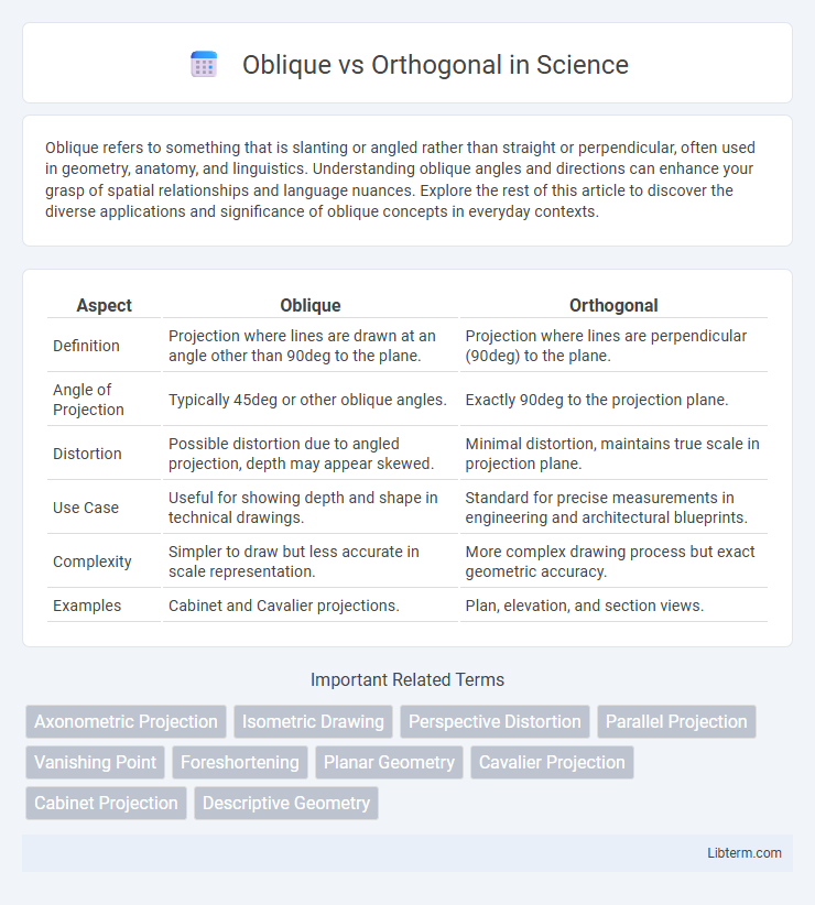
Oblique refers to something that is slanting or angled rather than straight or perpendicular, often used in geometry, anatomy, and linguistics. Understanding oblique angles and directions can enhance your grasp of spatial relationships and language nuances. Explore the rest of this article to discover the diverse applications and significance of oblique concepts in everyday contexts.
Table of Comparison
| Aspect | Oblique | Orthogonal |
|---|---|---|
| Definition | Projection where lines are drawn at an angle other than 90deg to the plane. | Projection where lines are perpendicular (90deg) to the plane. |
| Angle of Projection | Typically 45deg or other oblique angles. | Exactly 90deg to the projection plane. |
| Distortion | Possible distortion due to angled projection, depth may appear skewed. | Minimal distortion, maintains true scale in projection plane. |
| Use Case | Useful for showing depth and shape in technical drawings. | Standard for precise measurements in engineering and architectural blueprints. |
| Complexity | Simpler to draw but less accurate in scale representation. | More complex drawing process but exact geometric accuracy. |
| Examples | Cabinet and Cavalier projections. | Plan, elevation, and section views. |
Introduction to Oblique and Orthogonal
Oblique and orthogonal projections are two fundamental types of parallel projections used in technical drawing and computer graphics to represent three-dimensional objects on two-dimensional surfaces. Orthogonal projection features projections perpendicular to the projection plane, ensuring true shape and scale representation without distortion, commonly used in architectural and engineering plans. Oblique projection, characterized by projecting lines at an angle other than 90 degrees to the plane, allows more visual information on an object's front face, making it useful for illustrating complex details with a pseudo-3D effect.
Defining Oblique and Orthogonal Concepts
Oblique refers to lines or directions that are slanted or angled but not perpendicular or parallel, often creating dynamic and unconventional spatial relationships. Orthogonal describes elements positioned at right angles (90 degrees) to each other, emphasizing structure, clarity, and spatial order. Defining these concepts is crucial in fields such as geometry, design, and architecture for distinguishing between angled versus perpendicular alignment and their impact on visual composition and function.
Key Differences Between Oblique and Orthogonal
Oblique projections display objects with angled lines that are not perpendicular, offering a distorted but visually accessible view, whereas orthogonal projections use perpendicular lines to present accurate dimensions without distortion. Oblique projection maintains one face of the object parallel to the viewing plane, allowing depth to be represented at an angle, while orthogonal projection maps views directly onto planes at right angles to the object. The key differences lie in angle measurement, distortion levels, and application methods, with oblique favored for quick sketches and orthogonal preferred for precise engineering drawings.
Mathematical Foundations: Oblique vs Orthogonal
Oblique and orthogonal vectors differ fundamentally in their angular relationships and inner product properties; orthogonal vectors have a zero dot product indicating perpendicularity, while oblique vectors form non-right angles resulting in a non-zero dot product. In linear algebra, orthogonal vectors simplify computations as they maintain independence in Euclidean spaces, whereas oblique vectors do not guarantee this independence, complicating vector space decompositions. The mathematical significance lies in orthogonality providing an ideal basis for projections, eigenvalue problems, and Fourier analysis, contrasting with the more general, less constrained nature of oblique bases.
Applications in Geometry and Linear Algebra
Oblique and orthogonal vectors play crucial roles in geometry and linear algebra, where orthogonal vectors are perpendicular with a dot product of zero, facilitating simplified projections and basis transformations. Oblique vectors, having non-right angles between them, enable the representation of skew coordinate systems and more general linear combinations. In applications such as solving linear systems, orthogonal bases improve numerical stability, while oblique bases can better model real-world scenarios involving non-orthogonal constraints.
Visual Representation and Interpretation
Oblique projection presents objects with a skewed angle, making one face visible in true shape while others are distorted, enhancing depth perception but reducing dimensional accuracy. Orthogonal projection displays objects with parallel lines perpendicular to the projection plane, preserving true dimensions and enabling accurate measurements without distortion. Visual interpretation of oblique projections is intuitive for conceptual understanding, whereas orthogonal projections are preferred for precise technical analysis and engineering design.
Advantages of Oblique Methods
Oblique methods in factor analysis allow factors to correlate, providing a more realistic representation of complex data structures where variables are interrelated, enhancing interpretability in psychological and social sciences. These methods often yield simpler, more meaningful factor patterns by accommodating underlying constructs that naturally overlap, compared to orthogonal methods which force uncorrelated factors. Oblique rotations such as Promax and Direct Oblimin improve model fit and data representation in multidimensional scaling and exploratory data analysis.
Benefits of Orthogonal Approaches
Orthogonal approaches offer clear benefits by minimizing interdependencies, which enhances modularity and simplifies troubleshooting in complex systems. These methods enable parallel development and testing, accelerating project timelines while reducing error propagation. Orthogonal designs also improve scalability and maintainability, ensuring long-term system robustness and adaptability.
Real-World Examples and Use Cases
Oblique projection is widely used in technical drawing and engineering to represent three-dimensional objects with a simple depth portrayal, ideal for furniture design and architectural sketches where visual clarity of front faces is essential. Orthogonal projection, prevalent in CAD software and manufacturing, provides accurate measurements by projecting images perpendicular to the plane, crucial for construction blueprints and mechanical parts fabrication requiring precise dimensions. Applications in video game design often combine both methods: oblique for stylistic isometric views and orthogonal for level design and collision detection mapping.
Choosing Between Oblique and Orthogonal
Choosing between oblique and orthogonal layouts depends on the project's spatial requirements and visual impact goals. Oblique designs offer dynamic angles and a sense of depth, enhancing visual interest in architectural and graphic contexts. Orthogonal layouts prioritize clarity and precision with right angles, making them ideal for technical drawings and structured floor plans that require exact measurements.
Oblique Infographic

 libterm.com