Frequency response measures how a system or device reacts to different frequencies of input signals, revealing its ability to reproduce sound or data accurately across the spectrum. Understanding frequency response helps optimize audio equipment performance, ensuring clarity and fidelity in your listening experience. Discover more about frequency response and its impact on your devices in the rest of this article.
Table of Comparison
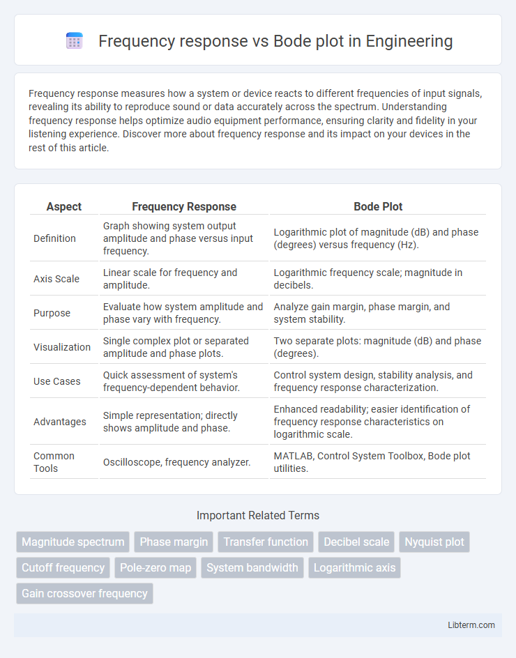
| Aspect | Frequency Response | Bode Plot |
|---|---|---|
| Definition | Graph showing system output amplitude and phase versus input frequency. | Logarithmic plot of magnitude (dB) and phase (degrees) versus frequency (Hz). |
| Axis Scale | Linear scale for frequency and amplitude. | Logarithmic frequency scale; magnitude in decibels. |
| Purpose | Evaluate how system amplitude and phase vary with frequency. | Analyze gain margin, phase margin, and system stability. |
| Visualization | Single complex plot or separated amplitude and phase plots. | Two separate plots: magnitude (dB) and phase (degrees). |
| Use Cases | Quick assessment of system's frequency-dependent behavior. | Control system design, stability analysis, and frequency response characterization. |
| Advantages | Simple representation; directly shows amplitude and phase. | Enhanced readability; easier identification of frequency response characteristics on logarithmic scale. |
| Common Tools | Oscilloscope, frequency analyzer. | MATLAB, Control System Toolbox, Bode plot utilities. |
Introduction to Frequency Response and Bode Plots
Frequency response characterizes how a system reacts to different input signal frequencies, providing insights into gain and phase variations essential for control system analysis. Bode plots graphically represent this frequency response with two logarithmic plots: magnitude (gain) and phase angle versus frequency, facilitating the assessment of system stability and performance. These plots are critical in designing and tuning feedback controllers, highlighting resonance frequencies and phase margins.
Defining Frequency Response in Systems
Frequency response defines a system's output spectrum relative to sinusoidal input signals across varying frequencies, characterizing gain and phase shift. It captures how systems like filters or amplifiers behave dynamically, revealing resonant peaks and attenuation regions. Bode plots graphically represent this response by plotting magnitude (in dB) and phase (in degrees) versus logarithmic frequency, enabling intuitive system analysis and design optimization.
What is a Bode Plot?
A Bode plot is a graphical representation used in engineering and control systems to analyze the frequency response of a linear, time-invariant system. It consists of two plots: one showing the magnitude (gain) versus frequency on a logarithmic scale, and the other displaying the phase shift versus frequency. This visualization helps engineers assess system stability, bandwidth, and gain and phase margins for designing and tuning feedback controllers.
Key Differences Between Frequency Response and Bode Plot
Frequency response characterizes a system's output magnitude and phase shift over a range of input frequencies, providing a direct, often experimental, measurement. Bode plots represent frequency response data in two logarithmic graphs--magnitude (in decibels) and phase (in degrees)--facilitating easier analysis and design in control systems and signal processing. Unlike raw frequency response data, Bode plots emphasize asymptotic approximations and engineering insights like gain margin and phase margin for stability assessment.
Importance of Frequency Response Analysis
Frequency response analysis is crucial for understanding how systems behave over a range of frequencies, revealing stability and performance characteristics vital for control systems and electronic filter design. Frequency response provides detailed amplitude and phase information, while Bode plots graphically represent this data with logarithmic frequency scales, making trends and critical frequency points easier to interpret. Engineers rely on frequency response analysis to optimize system robustness, minimize distortion, and ensure reliable operation under varying signal conditions.
Bode Plot Components: Magnitude and Phase
A Bode plot consists of two key components: the magnitude plot, which represents the gain of a system in decibels (dB) across a range of frequencies, and the phase plot, showing the phase shift in degrees between the input and output signals. The magnitude plot reveals how much a system amplifies or attenuates signals at various frequencies, while the phase plot indicates the timing difference introduced by the system. These components together provide a comprehensive frequency response analysis crucial for control system design and stability assessment.
Interpreting Frequency Response Data
Frequency response data illustrates how a system reacts across a spectrum of frequencies, showcasing amplitude and phase variations critical for stability analysis. Bode plots represent this data on logarithmic scales with two separate graphs: magnitude (in dB) and phase (in degrees), enabling easier identification of gain margins and phase margins. Interpreting these plots involves assessing resonant peaks, bandwidth, and phase shifts to optimize control strategies and ensure robust system performance.
Applications of Bode Plots in Engineering
Bode plots are extensively used in engineering to analyze the frequency response of linear time-invariant (LTI) systems, particularly in control system design and stability assessment. They enable engineers to graphically determine gain margin, phase margin, and bandwidth, facilitating the tuning of controllers such as PID to achieve desired performance and robustness. Additionally, Bode plots assist in characterizing filters, amplifiers, and feedback loops by illustrating how input signals of varying frequencies affect system output.
Limitations of Frequency Response and Bode Plots
Frequency response analysis can be limited by its inability to capture nonlinear system behaviors, resulting in inaccurate representations for systems with significant harmonics or time-variant characteristics. Bode plots, while effective for linear time-invariant systems, often fail to reveal system instabilities caused by delays or nonlinearities and can be challenging to interpret in the presence of noise. Both methods may oversimplify complex system dynamics, limiting their usefulness in detailed control system design or performance prediction under varying real-world conditions.
Choosing the Right Analysis: Frequency Response vs Bode Plot
Frequency response analysis offers a direct visualization of a system's magnitude and phase over a range of frequencies, ideal for assessing real-world signal behavior. Bode plots, presenting logarithmic frequency scales with separate magnitude and phase graphs, are essential for control system design and stability margin evaluation. Selecting between these methods depends on whether clarity in stability margins or intuitive signal characterization drives the analysis requirements.
Frequency response Infographic