A Cuk converter is a type of DC-DC power converter that efficiently transfers energy with a negative polarity output voltage, combining both step-up and step-down voltage capabilities. Its unique design uses an inductor and a capacitor to smooth current and reduce ripple, ensuring stable power supply in various electronic applications. Discover how this versatile converter can optimize Your power systems by exploring the detailed functions and benefits outlined in the rest of the article.
Table of Comparison
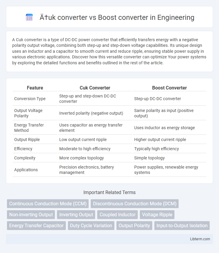
| Feature | Cuk Converter | Boost Converter |
|---|---|---|
| Conversion Type | Step-up and step-down DC-DC converter | Step-up DC-DC converter |
| Output Voltage Polarity | Inverted polarity (negative output) | Same polarity as input (positive output) |
| Energy Transfer Method | Uses capacitor as energy transfer element | Uses inductor as energy storage |
| Output Ripple | Low output current ripple | Higher output current ripple |
| Efficiency | Moderate to high efficiency | Typically high efficiency |
| Complexity | More complex topology | Simple topology |
| Applications | Precision electronics, battery management | Power supplies, renewable energy systems |
Overview of Ćuk and Boost Converters
The Cuk converter features a unique topology that transfers energy through a capacitor, providing continuous input and output currents with low ripple, making it suitable for applications requiring smooth power delivery. In contrast, the Boost converter steps up voltage from a lower input to a higher output by storing energy in an inductor and releasing it to the load, commonly used in power supplies and battery-powered devices. Both converters serve voltage conversion needs but differ in efficiency, complexity, and output characteristics depending on specific application requirements.
Basic Operating Principles
The Cuk converter transfers energy through a capacitor, enabling continuous current on both input and output sides, which reduces current ripple compared to the boost converter that stores energy in an inductor and outputs a higher voltage than the input. The boost converter operates by switching an inductor between input voltage and ground, storing energy during the switch-on phase and releasing it to the output during the switch-off phase, resulting in a step-up voltage conversion. Unlike the boost converter, the Cuk converter can both step up or step down voltage with inversion, providing smoother current and voltage waveforms through its unique energy transfer mechanism.
Circuit Topologies Compared
The Cuk converter uses a combination of inductors and capacitors to transfer energy with continuous input and output currents, resulting in low ripple and allowing for voltage step-up or step-down with polarity inversion. The Boost converter employs a single inductor and switch configuration to increase output voltage above the input voltage, characterized by discontinuous input current and simpler topology. Cuk converter topologies are more complex but provide better performance in terms of current ripple and flexibility, while Boost converters offer straightforward design and higher efficiency for step-up voltage applications.
Voltage Conversion Capabilities
The Cuk converter provides a unique capability of both voltage step-up and step-down with an inverted output voltage polarity, making it ideal for applications requiring bipolar voltage rails. In contrast, the Boost converter primarily functions to increase input voltage to a higher output voltage without inversion, limiting its use to step-up voltage scenarios. The Cuk converter's ability to deliver continuous input and output currents reduces current ripple, enhancing efficiency compared to the inherently discontinuous current in Boost converters.
Efficiency Analysis
The Cuk converter demonstrates higher efficiency than the Boost converter due to its ability to provide continuous input and output currents, reducing electromagnetic interference and stress on components. Its energy transfer through a capacitor rather than an inductor minimizes switching losses, enhancing overall power conversion efficiency. In contrast, the Boost converter typically experiences higher conduction and switching losses, especially at higher duty cycles, leading to lower efficiency under similar operating conditions.
Output Ripple Characteristics
The Cuk converter provides significantly lower output voltage ripple compared to the Boost converter due to its unique energy transfer via a capacitor rather than an inductor alone. This capacitor-based energy transfer smooths current flow, reducing voltage ripple at the output. In contrast, the Boost converter's output ripple is higher because it relies on inductor current that directly affects the output voltage, leading to more pronounced fluctuations.
Component Stress and Reliability
Cuk converters typically experience lower component stress compared to Boost converters due to their continuous input and output current, resulting in reduced voltage and current ripple. The bidirectional energy transfer in Cuk converters enhances reliability by minimizing voltage spikes on switches and capacitors. In contrast, Boost converters endure higher stress on the switch and diode components, often decreasing overall reliability under high load or transient conditions.
Common Application Areas
Cuk converters excel in applications requiring continuous input and output current with low ripple, such as in battery-powered systems and renewable energy sources like solar power. Boost converters are widely used in scenarios needing voltage step-up, including portable electronics, LCD backlighting, and electric vehicle powertrains. Both converter types find roles in power management systems, but Cuk converters are preferred for noise-sensitive applications due to their inherent current ripple reduction.
Advantages and Drawbacks
Cuk converters offer the advantage of providing continuous input and output currents with low ripple, improving electromagnetic compatibility and reducing stress on source components, making them suitable for sensitive electronic applications. However, they usually require a more complex design with additional passive components, leading to larger size and potential efficiency losses compared to Boost converters, which boast simpler circuitry and higher efficiency in voltage step-up applications. The key drawback of Boost converters lies in their discontinuous input current and higher ripple, which can cause increased electromagnetic interference and stress on the power source.
Selection Criteria for Design
The selection criteria for designing a Cuk converter versus a Boost converter primarily depend on the desired output voltage polarity and ripple characteristics; Cuk converters provide both step-up and step-down voltage capabilities with continuous input and output currents, leading to lower electromagnetic interference. Boost converters are preferred for simple step-up voltage applications due to their straightforward design and higher efficiency at moderate voltage ratios but exhibit discontinuous input current causing more ripple. Designers must consider factors such as voltage gain requirements, current ripple tolerance, system complexity, and electromagnetic interference constraints when choosing between these converters.
Ćuk converter Infographic