Haigh diagrams visually represent the relationship between mean stress and alternating stress to predict fatigue failure in materials. They help engineers assess whether components can withstand cyclic loading under different stress conditions by plotting safe and failure regions. Discover how Haigh diagrams enhance your fatigue analysis and material design by exploring the full article.
Table of Comparison
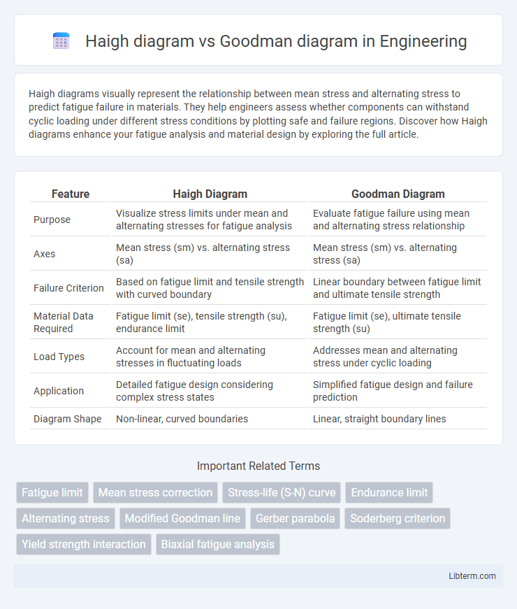
| Feature | Haigh Diagram | Goodman Diagram |
|---|---|---|
| Purpose | Visualize stress limits under mean and alternating stresses for fatigue analysis | Evaluate fatigue failure using mean and alternating stress relationship |
| Axes | Mean stress (sm) vs. alternating stress (sa) | Mean stress (sm) vs. alternating stress (sa) |
| Failure Criterion | Based on fatigue limit and tensile strength with curved boundary | Linear boundary between fatigue limit and ultimate tensile strength |
| Material Data Required | Fatigue limit (se), tensile strength (su), endurance limit | Fatigue limit (se), ultimate tensile strength (su) |
| Load Types | Account for mean and alternating stresses in fluctuating loads | Addresses mean and alternating stress under cyclic loading |
| Application | Detailed fatigue design considering complex stress states | Simplified fatigue design and failure prediction |
| Diagram Shape | Non-linear, curved boundaries | Linear, straight boundary lines |
Introduction to Fatigue Analysis
The Haigh diagram and Goodman diagram are essential tools in fatigue analysis for evaluating the combined effects of mean and alternating stresses on material durability. The Haigh diagram provides a graphical representation of stress states, incorporating mean and alternating stresses to predict fatigue failure under complex loading conditions. The Goodman diagram simplifies fatigue assessment by plotting allowable alternating stress against mean stress, aiding engineers in designing components resistant to fatigue crack initiation.
Overview of Haigh Diagram
The Haigh diagram provides a graphical representation of the relationship between mean stress and alternating stress to predict fatigue failure of materials under cyclic loading. It maps safe and failure zones by considering the interaction of mean stress, alternating stress, and material properties like yield strength and fatigue limit. Compared to the Goodman diagram, which linearly approximates fatigue limits, the Haigh diagram offers a more detailed and precise evaluation by incorporating nonlinear fatigue behavior and material-specific data.
Overview of Goodman Diagram
The Goodman diagram is a graphical representation used to evaluate the fatigue life of materials by relating mean stress and alternating stress to failure limits. It plots the maximum allowable stress combinations, combining tensile strength and endurance limit, to predict failure under cyclic loading conditions. This approach provides a conservative estimate of fatigue strength compared to the Haigh diagram, which incorporates more complex stress interaction considerations.
Fundamental Principles Behind Each Diagram
Haigh diagrams graphically represent stress components by plotting alternating stress versus mean stress to evaluate fatigue failure based on material endurance limits and yield strength. Goodman diagrams utilize a linear relationship between mean stress and alternating stress, incorporating ultimate tensile strength to predict fatigue life under variable loading conditions. Both diagrams serve as critical tools in fatigue analysis but differ fundamentally in their criteria for safe stress limits and failure prediction.
Key Differences Between Haigh and Goodman Diagrams
Haigh diagrams display stress interactions considering mean stress and alternating stress to evaluate fatigue life, while Goodman diagrams graphically represent failure criteria based on mean and alternating stresses using a linear failure line. Haigh diagrams provide a more precise representation for materials with non-linear behavior under cyclic loading, whereas Goodman diagrams assume a linear relationship between mean stress and fatigue strength. The key difference lies in Haigh's depiction of stress limits incorporating compressive mean stresses, contrasting with Goodman's approach which primarily accounts for tensile mean stresses in fatigue failure prediction.
Applications in Engineering and Design
Haigh diagrams effectively predict fatigue failure by illustrating the relationship between mean stress and alternating stress, making them essential for designing components subjected to cyclic loading in aerospace and automotive industries. Goodman diagrams are widely used to ensure safe design margins by combining mean and alternating stresses against material tensile strength, particularly in mechanical and structural engineering applications. Both tools optimize fatigue life and structural integrity by guiding engineers in selecting appropriate materials and stress limits for dynamic loading conditions.
Advantages and Limitations of Haigh Diagram
Haigh diagrams provide a visual representation of stress states combining mean and alternating stresses, facilitating easy determination of safe and failure regions in fatigue analysis. This approach offers clearer insight into complex loading scenarios compared to Goodman diagrams, which mainly address mean stress effects with less emphasis on alternating stress interactions. However, Haigh diagrams can be limited by their dependency on accurate material fatigue data and may become less practical for components experiencing multi-axial stress states or non-proportional loading conditions.
Advantages and Limitations of Goodman Diagram
The Goodman diagram offers a straightforward graphical method to evaluate fatigue failure by correlating mean stress and alternating stress, making it ideal for designing components under varying load conditions. Its primary advantage lies in its conservative approach, providing a clear failure boundary that simplifies safety assessments and reduces the risk of unexpected fatigue failure. However, the Goodman diagram tends to be overly simplistic, often underestimating fatigue life for materials with non-linear stress behaviors and neglecting factors like mean stress relaxation and variable amplitude loading, limiting its accuracy in complex real-world applications.
Selection Criteria: When to Use Haigh vs Goodman Diagram
Haigh diagrams are preferred for evaluating fatigue limits under combined mean and alternating stresses in materials with well-defined endurance limits, especially when zero mean stress behavior is critical. Goodman diagrams are more suitable for metals lacking a clear endurance limit, focusing on linear failure criteria combining mean and alternating stresses for design against fatigue failure. Selection depends on material properties and fatigue data availability, with Haigh diagrams favored for ferrous materials and Goodman diagrams commonly applied in non-ferrous alloys and brittle materials.
Conclusion and Practical Recommendations
The Haigh diagram provides a comprehensive visualization of stress interaction under combined mean and alternating stresses, making it ideal for fatigue analysis in ductile materials. The Goodman diagram simplifies these relationships into a linear failure criterion, offering practical ease for design but possibly conservative estimates for alternating stress limits. Engineers should use the Haigh diagram for more precise fatigue life predictions in complex loading scenarios and rely on the Goodman diagram for quick, conservative assessments during preliminary design phases.
Haigh diagram Infographic