Fall time brings vibrant foliage, crisp air, and cozy moments perfect for outdoor activities and seasonal treats. Embracing this season allows you to reconnect with nature's transformation and enjoy a peaceful atmosphere. Dive deeper into the joys of fall time in the rest of the article.
Table of Comparison
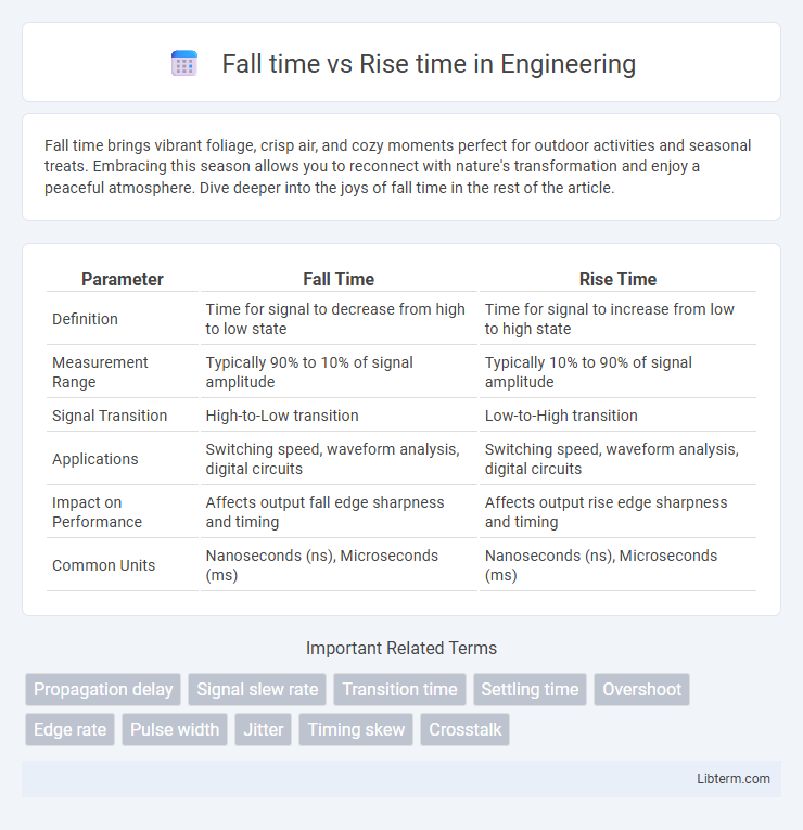
| Parameter | Fall Time | Rise Time |
|---|---|---|
| Definition | Time for signal to decrease from high to low state | Time for signal to increase from low to high state |
| Measurement Range | Typically 90% to 10% of signal amplitude | Typically 10% to 90% of signal amplitude |
| Signal Transition | High-to-Low transition | Low-to-High transition |
| Applications | Switching speed, waveform analysis, digital circuits | Switching speed, waveform analysis, digital circuits |
| Impact on Performance | Affects output fall edge sharpness and timing | Affects output rise edge sharpness and timing |
| Common Units | Nanoseconds (ns), Microseconds (ms) | Nanoseconds (ns), Microseconds (ms) |
Introduction to Fall Time and Rise Time
Fall time and rise time are critical parameters in signal processing that measure the transition speed of a waveform between voltage levels. Rise time quantifies the duration for a signal to increase from 10% to 90% of its peak amplitude, while fall time measures the time taken to decrease from 90% to 10%. These metrics are essential for evaluating the performance of electronic components and systems, impacting signal integrity and timing accuracy.
Definition and Key Concepts
Fall time refers to the duration taken for a signal to transition from a high voltage level (typically 90%) down to a low voltage level (usually 10%), indicating how quickly a signal decreases. Rise time measures the period for the signal to move from a low voltage level (commonly 10%) up to a high voltage level (generally 90%), representing how fast a signal increases. Both metrics are crucial in electronics and signal processing for evaluating the speed and quality of voltage transitions in digital and analog circuits.
Importance in Signal Processing
Fall time and rise time are critical parameters in signal processing that determine the speed at which a signal transitions between logic levels, directly impacting signal integrity and timing accuracy. Precise measurement and control of these times ensure minimal distortion and reduce the likelihood of errors in high-frequency digital circuits and communication systems. Optimizing fall and rise times enhances overall system performance by improving signal fidelity and synchronization.
Mathematical Representation
Fall time (tf) and rise time (tr) are critical parameters in signal processing, quantitatively defined using the time intervals for a waveform to transition between specific voltage levels, typically 10% to 90% for rise time and 90% to 10% for fall time. Mathematically, rise time tr = t90% - t10% measures the duration for a signal to increase from 10% to 90% of its final value, while fall time tf = t10% - t90% represents the time to decrease from 90% to 10%. These parameters are often modeled using exponential or linear approximations in transient analysis equations, providing insights into the dynamic response and bandwidth of electronic circuits.
Differences Between Fall Time and Rise Time
Fall time and rise time are critical parameters in signal processing that describe the transitions of a waveform; rise time measures the duration for a signal to increase from 10% to 90% of its maximum value, while fall time measures the time it takes to decrease from 90% to 10%. The primary difference lies in their directional transition: rise time captures the signal's upward slope during a rising edge, whereas fall time captures the downward slope during a falling edge, which can affect signal integrity and timing analysis differently. These metrics are essential for characterizing high-speed digital circuits, where faster rise and fall times typically correlate with enhanced performance and reduced signal distortion.
Factors Affecting Fall and Rise Times
Fall time and rise time in electronic signals are influenced by factors such as circuit capacitance, resistance, and the bandwidth of the system. Increased parasitic capacitance or resistance slows down the charging and discharging processes, leading to longer rise and fall times. The type of semiconductor device and its switching characteristics also significantly impact the speed at which signals transition between voltage levels.
Applications in Electronics and Communication
Fall time and rise time are critical parameters in electronics and communication systems, influencing signal integrity and timing accuracy. Fast rise and fall times improve the performance of digital circuits by enabling higher data rates and reducing signal distortion in high-speed communication interfaces. Precise control of these times is essential in applications such as oscilloscopes, transmitters, and pulse shaping to ensure reliable data transmission and minimize electromagnetic interference.
Measurement Techniques
Fall time and rise time are critical parameters in signal integrity analysis, representing the intervals for a signal to transition between defined voltage levels. Measurement techniques for these time intervals typically involve high-speed oscilloscopes and time-domain reflectometry to capture transient voltage changes with nanosecond precision. Accurate assessment relies on calibrated probes and bandwidth considerations, ensuring that the recorded data reflects true signal behavior without distortion or measurement artifacts.
Impact on System Performance
Fall time and rise time directly affect system performance by determining signal speed and accuracy in digital circuits. Shorter rise and fall times improve switching speed, reducing propagation delay and increasing overall system responsiveness. However, excessively fast transitions can cause signal integrity issues such as ringing and electromagnetic interference, necessitating a balance in timing parameters for optimal performance.
Best Practices for Optimizing Fall and Rise Times
Optimizing fall and rise times involves minimizing signal transition delays to enhance circuit performance and reduce power consumption. Best practices include using appropriate driver strength, minimizing capacitive loading, and implementing controlled impedance routing to ensure signal integrity. Employing slew rate control techniques and proper buffer placement further refines timing characteristics, promoting faster and more reliable signal transitions.
Fall time Infographic