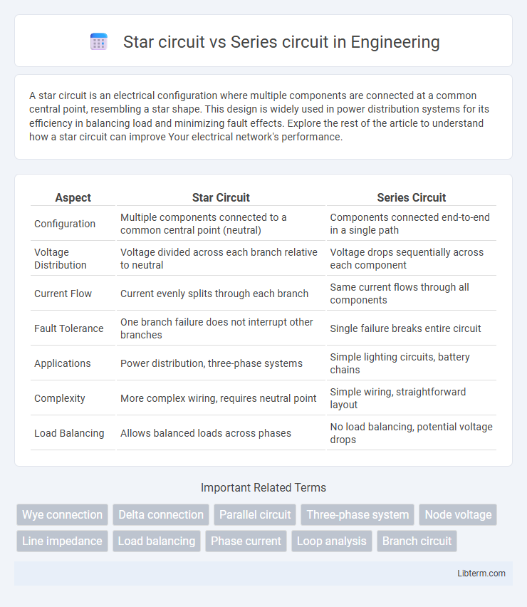
A star circuit is an electrical configuration where multiple components are connected at a common central point, resembling a star shape. This design is widely used in power distribution systems for its efficiency in balancing load and minimizing fault effects. Explore the rest of the article to understand how a star circuit can improve Your electrical network's performance.
Table of Comparison
| Aspect | Star Circuit | Series Circuit |
|---|---|---|
| Configuration | Multiple components connected to a common central point (neutral) | Components connected end-to-end in a single path |
| Voltage Distribution | Voltage divided across each branch relative to neutral | Voltage drops sequentially across each component |
| Current Flow | Current evenly splits through each branch | Same current flows through all components |
| Fault Tolerance | One branch failure does not interrupt other branches | Single failure breaks entire circuit |
| Applications | Power distribution, three-phase systems | Simple lighting circuits, battery chains |
| Complexity | More complex wiring, requires neutral point | Simple wiring, straightforward layout |
| Load Balancing | Allows balanced loads across phases | No load balancing, potential voltage drops |
Introduction to Star and Series Circuits
Star circuits feature three loads connected at a common central point, allowing voltage to be divided among each branch, making them essential in three-phase power systems for balanced load distribution. Series circuits consist of components connected end-to-end, where the same current flows through each element, resulting in voltage drops that sum up across the circuit. Understanding the fundamental differences between star and series circuits is crucial for designing efficient electrical systems and optimizing power delivery.
Fundamental Principles of Star Circuits
Star circuits, also known as Y circuits, connect three components to a common central point called the neutral, enabling balanced voltage distribution across each phase. Each phase voltage in a star circuit is lower than the line voltage by a factor of 3, which improves safety and efficiency in power transmission. The fundamental principles of star circuits include neutral point grounding, phase voltage equality, and the ability to handle unbalanced loads without significant voltage distortion.
Basic Structure of Series Circuits
A series circuit consists of components connected end-to-end in a single path, ensuring the same current flows through all elements. The basic structure includes resistors or other devices linked sequentially between a voltage source's positive and negative terminals. This arrangement results in the total resistance equaling the sum of individual resistances, affecting the overall current and voltage distribution.
Key Differences Between Star and Series Circuits
Star circuits feature multiple components connected to a common central point, providing independent paths for current flow, whereas series circuits have components connected end-to-end, offering a single current path. Voltage in a star circuit is divided across each branch independently, while in a series circuit, the total voltage is shared sequentially among all components. Star circuits improve reliability by isolating faults in individual branches, unlike series circuits where a fault in one element interrupts the entire current flow.
Electrical Characteristics in Star vs Series Circuits
Star circuits feature a common neutral point allowing voltage distribution to be divided equally across loads, resulting in lower phase currents and improved stability under unbalanced load conditions. Series circuits maintain the same current throughout all components, with voltages dropping proportionally according to each component's resistance, leading to simpler current calculations but potential voltage instability with varying loads. In terms of power distribution, star circuits support both line-to-line and line-to-neutral voltage supplies, enhancing versatility compared to the single voltage pathway in series circuits.
Applications of Star Circuits in Industry
Star circuits are extensively used in industrial three-phase power systems to enable stable voltage distribution and reduce the risk of equipment damage by providing a neutral point for grounding. They are commonly applied in electrical distribution networks, particularly for supplying power to lighting systems and low-voltage loads requiring a neutral connection. Industries also leverage star-configured transformers and motors to achieve efficient and safe operation in manufacturing plants and large commercial buildings.
Common Uses of Series Circuits in Everyday Life
Series circuits are commonly used in applications where the same current must flow through all components, such as in string lights, where bulbs connected in series ensure uniform brightness until one bulb fails. They are also found in simple electrical devices like flashlights and some battery-operated toys, where the total voltage is the sum of the individual cell voltages aligned in series. This configuration facilitates easy troubleshooting and ensures energy efficiency in low-power applications.
Advantages and Limitations of Star Circuits
Star circuits provide the advantage of a neutral point, allowing for stable voltage and easy grounding in electrical systems. They enable the use of both single-phase and three-phase loads, improving system flexibility and reducing the risk of voltage imbalance. However, star circuits face limitations such as lower phase voltage compared to series circuits and potential neutral conductor overloads under unbalanced conditions.
Pros and Cons of Series Circuits
Series circuits provide a simple and cost-effective design, making them ideal for basic electrical applications by ensuring the same current flows through all components. However, their major drawback is that if one component fails or is disconnected, the entire circuit is interrupted, leading to a complete loss of functionality. Voltage division across components can also reduce the performance of individual devices in a series circuit, limiting its use in complex systems requiring consistent voltage.
Safety Considerations for Star and Series Circuit Designs
Star circuit designs enhance safety by providing a neutral point that stabilizes voltage and limits fault currents, reducing the risk of electric shock and equipment damage. Series circuits pose higher safety risks due to the continuous current path, where a single fault can disrupt the entire system and cause overheating or potential fire hazards. Proper insulation and protective devices are critical in both designs, but star circuits allow easier fault detection and isolation, improving overall electrical safety.
Star circuit Infographic