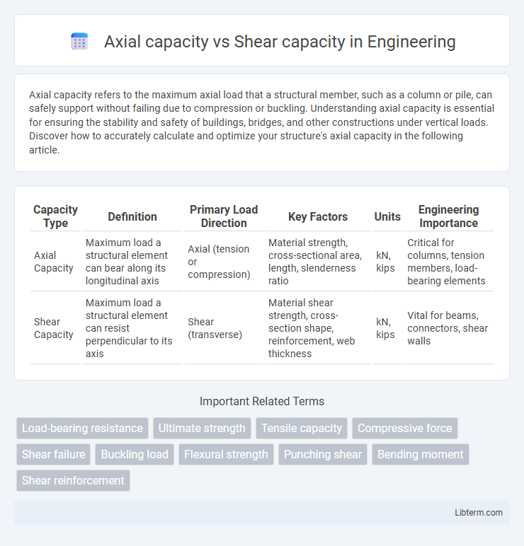
Axial capacity refers to the maximum axial load that a structural member, such as a column or pile, can safely support without failing due to compression or buckling. Understanding axial capacity is essential for ensuring the stability and safety of buildings, bridges, and other constructions under vertical loads. Discover how to accurately calculate and optimize your structure's axial capacity in the following article.
Table of Comparison
| Capacity Type | Definition | Primary Load Direction | Key Factors | Units | Engineering Importance |
|---|---|---|---|---|---|
| Axial Capacity | Maximum load a structural element can bear along its longitudinal axis | Axial (tension or compression) | Material strength, cross-sectional area, length, slenderness ratio | kN, kips | Critical for columns, tension members, load-bearing elements |
| Shear Capacity | Maximum load a structural element can resist perpendicular to its axis | Shear (transverse) | Material shear strength, cross-section shape, reinforcement, web thickness | kN, kips | Vital for beams, connectors, shear walls |
Introduction to Axial and Shear Capacity
Axial capacity refers to the maximum load a structural member can withstand along its longitudinal axis without failure, primarily influenced by material strength and cross-sectional area. Shear capacity defines the ability of a member to resist forces that cause sliding between adjacent internal planes, depending on material shear strength and geometric properties. Understanding the distinction between axial and shear capacity is essential for designing safe and efficient structural elements under combined loading conditions.
Definitions: Axial Capacity vs Shear Capacity
Axial capacity refers to the maximum load a structural element can support along its longitudinal axis without failure, primarily resisting compression or tension forces. Shear capacity denotes the maximum load a material or component can withstand parallel to its cross-section, preventing shear failure caused by forces acting tangentially. Understanding these definitions is crucial for designing safe and efficient structural systems, ensuring stability under combined loading conditions.
Importance in Structural Engineering
Axial capacity determines a structural element's ability to withstand compressive or tensile loads along its length, ensuring stability and preventing buckling. Shear capacity measures the element's resistance to forces that cause sliding between material planes, critical for avoiding shear failure and maintaining structural integrity. Understanding both capacities is essential for designing safe structures that can support expected loads without deformation or collapse.
Factors Influencing Axial Capacity
Axial capacity is primarily influenced by factors such as the cross-sectional area, material strength, and the slenderness ratio of the structural element, which determine its ability to withstand compressive loads without buckling. Concrete strength, steel reinforcement ratio, column length, and end conditions critically affect the axial load-bearing capability. In contrast, shear capacity is largely determined by shear reinforcement, concrete shear strength, and the geometry of the cross-section, emphasizing the distinct parameters controlling axial versus shear capacities.
Factors Influencing Shear Capacity
Shear capacity depends heavily on factors such as concrete strength, reinforcement type and arrangement, and the presence of transverse ties or stirrups that help resist diagonal shear forces. The size and shape of the cross-section, as well as the type of loading conditions and support restraints, significantly influence the overall shear resistance. Unlike axial capacity, which primarily relies on compressive strength and cross-sectional area, shear capacity is more sensitive to shear span-to-depth ratio and the effectiveness of shear reinforcement in preventing brittle failure.
Methods for Calculating Axial Capacity
Methods for calculating axial capacity typically involve evaluating the load-bearing potential of structural elements under compressive forces, emphasizing factors such as material strength, cross-sectional area, and effective length. Common approaches include using empirical formulas, finite element analysis, and code-based equations like those found in AISC or Eurocode, which incorporate parameters such as buckling resistance and strain limits. These methods provide a critical assessment of maximum axial loads before failure, distinct from shear capacity calculations that focus on transverse force resistance and shear stress distribution.
Methods for Calculating Shear Capacity
Methods for calculating shear capacity primarily include empirical formulas, finite element analysis (FEA), and design codes such as ACI 318 or Eurocode 2. Empirical formulas often consider shear reinforcement, concrete strength, and load conditions to estimate the shear capacity of beams or columns. Finite element analysis provides a detailed numerical simulation of stress and strain distribution, improving the accuracy of shear capacity prediction in complex structural elements.
Common Failure Modes: Axial vs Shear
Axial capacity failure commonly occurs due to crushing or buckling of structural members, where compressive loads exceed material strength or stability limits. Shear capacity failure is often characterized by diagonal tension cracking or shear sliding, caused by shear stresses surpassing the shear strength of the material or connections. Understanding these distinct failure modes is crucial for designing safe columns and beams that effectively resist both axial and shear forces.
Design Considerations and Code Requirements
Axial capacity primarily governs the maximum load a structural element can sustain along its length, while shear capacity determines the element's ability to resist transverse forces without failure. Design considerations require careful evaluation of load combinations, material strength, and cross-sectional properties to ensure both capacities meet or exceed specified safety margins per code requirements such as AISC 360 or Eurocode 3. Compliance with these standards ensures balanced interaction between axial and shear forces, preventing brittle or ductile failure modes through appropriate reinforcement and detailing.
Practical Applications and Case Studies
Axial capacity, defined by the maximum load a structural element can support along its longitudinal axis, is critical in designing columns and piles to prevent buckling or crushing failures in high-rise buildings and bridge piers. Shear capacity, representing the material's resistance to forces acting parallel to the cross-section, is paramount in beams and slabs to avoid diagonal tension or shear cracking observed in highway overpasses and industrial flooring. Case studies in seismic retrofitting projects highlight the necessity to optimize both axial and shear capacities for structural resilience, demonstrating enhanced performance when reinforced concrete columns are designed with adequate shear reinforcement alongside axial load considerations.
Axial capacity Infographic

 libterm.com