The polar axis plays a crucial role in astronomy and navigation, serving as the imaginary line around which the Earth rotates and aligning with the planet's geographic poles. Understanding the polar axis is essential for accurately tracking celestial objects and for the precise calibration of telescopes and other observational instruments. Explore the rest of the article to learn how the polar axis affects your stargazing and navigation experience.
Table of Comparison
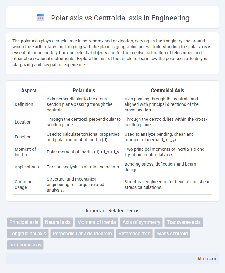
| Aspect | Polar Axis | Centroidal Axis |
|---|---|---|
| Definition | Axis perpendicular to the cross-section plane passing through the centroid. | Axis passing through the centroid and aligned with principal directions of the cross-section. |
| Location | Through the centroid, perpendicular to section plane. | Through the centroid, lies within the cross-section plane. |
| Function | Used to calculate torsional properties and polar moment of inertia (J). | Used to analyze bending, shear, and moment of inertia (I_x, I_y). |
| Moment of Inertia | Polar moment of inertia (J) = I_x + I_y. | Two principal moments of inertia, I_x and I_y, about centroidal axes. |
| Applications | Torsion analysis in shafts and beams. | Bending stress, deflection, and beam design. |
| Common Usage | Structural and mechanical engineering for torque-related analysis. | Structural engineering for flexural and shear stress calculations. |
Introduction to Polar Axis and Centroidal Axis
The polar axis is an imaginary line perpendicular to the plane of a cross-section, used to calculate torsional stresses and moments of inertia called polar moments. The centroidal axis passes through the centroid, the geometric center of the area, and is crucial in determining bending stresses and sectional properties such as the moment of inertia about the centroidal axis. Understanding these axes helps engineers analyze and design structural elements subjected to bending, torsion, and combined loads.
Defining the Polar Axis in Mechanics
The polar axis in mechanics is an imaginary line passing through the centroid of a cross-section around which the polar moment of inertia is calculated, representing resistance to torsional loading. It differs from the centroidal axis, which refers to the principal axes passing through the centroid for bending moments. The polar axis is crucial for analyzing shear stresses in circular shafts and determining torsional rigidity.
Understanding the Centroidal Axis
The centroidal axis is a crucial reference line passing through the centroid of a cross-section, where the area is evenly distributed on either side, ensuring neutral bending stress during flexure. It serves as the baseline for calculating moments of inertia and stress distribution in structural elements, differing from the polar axis which involves rotational properties around a point. Understanding the centroidal axis allows engineers to accurately analyze bending behavior and optimize structural design for stability and strength.
Key Differences Between Polar Axis and Centroidal Axis
The polar axis refers to an axis about which polar moments of inertia are calculated, typically passing through the centroid and perpendicular to the plane of a cross-section, while the centroidal axis lies within the plane of the section and passes through its centroid. The key difference lies in their orientation: the centroidal axis is used for bending stress analysis along principal directions, whereas the polar axis is essential for torsional and polar moment of inertia calculations. Understanding these distinctions is critical in structural engineering and mechanics for accurate stress and deformation assessment of beams and shafts.
Mathematical Representation of Each Axis
The polar axis is mathematically represented by the integral of the moment of inertia about a point, often expressed as \( I_p = I_x + I_y \), where \( I_x \) and \( I_y \) are moments of inertia about perpendicular centroidal axes. The centroidal axis passes through the centroid of the area or mass, and its moment of inertia is calculated by integrating \( r^2 \, dm \) or \( r^2 \, dA \) where \( r \) is the perpendicular distance from the axis to the element \( dm \) or \( dA \). The polar moment of inertia combines the contributions of both perpendicular centroidal axes, crucial in torsional analysis, while centroidal moments of inertia are fundamental in bending and deflection calculations.
Importance in Structural Analysis
The polar axis is crucial in structural analysis for calculating torsional stresses and understanding rotational behavior of cross-sections under twisting loads. The centroidal axis serves as the reference line passing through the centroid, essential for determining bending stresses and deflections in beams subjected to bending moments. Accurate identification of both axes ensures precise stress distribution analysis, which is vital for designing safe and efficient structural elements.
Role in Moment of Inertia Calculations
The polar axis plays a crucial role in calculating the polar moment of inertia, which measures an object's resistance to torsional deformation around an axis perpendicular to its cross-section. The centroidal axis, located at the geometric center of a cross-section, is essential for determining the moments of inertia that quantify bending resistance around principal axes. Accurate moment of inertia calculations depend on identifying the correct axis--polar for torsion and centroidal for bending--to ensure precise structural analysis and design.
Real-World Applications in Engineering
The polar axis and centroidal axis both play crucial roles in engineering design, particularly in structural and mechanical analysis. The polar axis is essential for calculating torsional stresses and moments of inertia in components subjected to twisting, such as shafts and circular beams, while the centroidal axis provides a reference for bending stress analysis and deflection calculations in beams and structural elements. Engineers leverage these axes to optimize material distribution and ensure safety and performance in bridges, automotive parts, and aerospace structures.
Advantages and Limitations of Each Axis
The polar axis facilitates calculation of torsional stresses and is advantageous for analyzing circular shafts due to its relation to polar moment of inertia, but it simplifies non-circular cross-sections less effectively. The centroidal axis provides accurate bending stress analysis by passing through a section's center of mass, which is beneficial for beams and symmetrical sections; however, it may require additional transformations for complex shapes and combined loading conditions. Both axes serve distinct structural analysis purposes, with the polar axis excelling in torsion and the centroidal axis in bending, but their effectiveness depends on cross-sectional geometry and load type.
Summary: Choosing the Right Axis for Analysis
The polar axis is ideal for analyzing torsional stresses and moments of inertia in circular or cylindrical structures, while the centroidal axis is crucial for evaluating bending stresses and shear forces in beams and symmetrical cross-sections. Understanding the location of the centroid and polar centroid facilitates accurate computation of section properties and stress distribution. Selecting the appropriate axis based on geometry and load conditions ensures precise structural analysis and optimized design performance.
Polar axis Infographic