Oblique projection is a drawing technique used in technical and engineering graphics to represent three-dimensional objects on two-dimensional surfaces, where the front face is drawn true to scale while the depth is projected at an angle, typically 45 degrees. This method allows your visual interpretation of objects to maintain clarity by distorting only the depth dimension, making complex shapes easier to understand. Explore the rest of the article to discover how oblique projection can enhance your design and visualization skills.
Table of Comparison
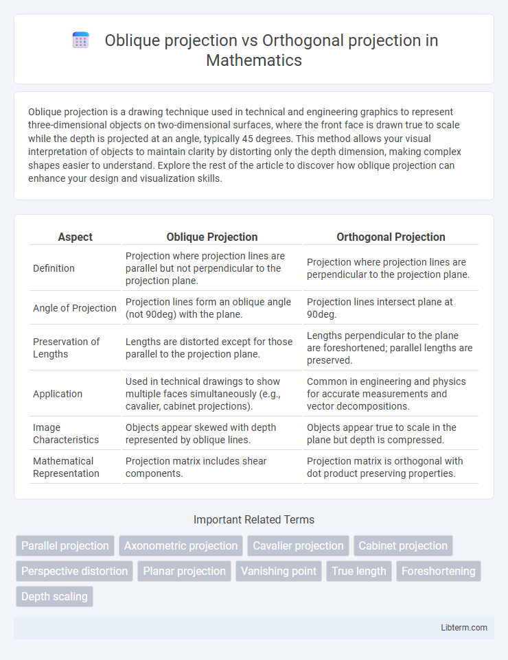
| Aspect | Oblique Projection | Orthogonal Projection |
|---|---|---|
| Definition | Projection where projection lines are parallel but not perpendicular to the projection plane. | Projection where projection lines are perpendicular to the projection plane. |
| Angle of Projection | Projection lines form an oblique angle (not 90deg) with the plane. | Projection lines intersect plane at 90deg. |
| Preservation of Lengths | Lengths are distorted except for those parallel to the projection plane. | Lengths perpendicular to the plane are foreshortened; parallel lengths are preserved. |
| Application | Used in technical drawings to show multiple faces simultaneously (e.g., cavalier, cabinet projections). | Common in engineering and physics for accurate measurements and vector decompositions. |
| Image Characteristics | Objects appear skewed with depth represented by oblique lines. | Objects appear true to scale in the plane but depth is compressed. |
| Mathematical Representation | Projection matrix includes shear components. | Projection matrix is orthogonal with dot product preserving properties. |
Introduction to Projection Methods
Oblique projection displays objects with parallel lines that are drawn at an angle to the projection plane, offering a pictorial representation where depth is skewed but dimensions remain measurable. Orthogonal projection uses perpendicular projection lines to the plane, resulting in true shape and scale views, commonly employed in engineering and architectural drawings. These methods differ in how they represent spatial information, with oblique emphasizing visual depth and orthogonal prioritizing accurate dimensionality.
Defining Oblique Projection
Oblique projection is a graphic technique where objects are represented with parallel lines drawn at an angle to the projection plane, allowing the front face to appear in true scale while depth is distorted. Unlike orthogonal projection, which uses perpendicular projectors to represent objects in true scale along all axes, oblique projection simplifies visualization by combining frontal accuracy with a stylized depth effect. Common types of oblique projection include Cavalier and Cabinet projections, differing in the angle and scale of the receding axis.
Understanding Orthogonal Projection
Orthogonal projection is a method in computer graphics and technical drawing where a three-dimensional object is represented on a two-dimensional plane using perpendicular projection lines, preserving true dimensions and shapes without distortion. It differs from oblique projection, which projects points along parallel lines at an angle, causing depth distortion for a more pictorial view. Understanding orthogonal projection is essential for engineering and architectural drawings because it provides accurate measurements and facilitates precise construction and analysis.
Key Differences Between Oblique and Orthogonal Projection
Oblique projection displays objects where the front face is shown in true scale and angles are distorted, making depth appear skewed, whereas orthogonal projection represents objects with perpendicular projection lines, preserving true dimensions without distortion. In oblique projection, the depth axis is drawn at an angle typically 45 degrees, creating a visual depth effect, while orthogonal projection uses parallel lines perpendicular to the projection plane to maintain accurate scale and shape. Orthogonal projection is preferred in engineering for precise measurements, whereas oblique projection is often used in artistic and technical illustrations for quick visualization of depth.
Mathematical Principles Involved
Oblique projection employs parallel lines at an angle other than 90 degrees to the projection plane, combining frontal faces with scaled receding dimensions, which mathematically distorts depth for visual emphasis. Orthogonal projection relies on perpendicular projection rays intersecting the projection plane at right angles, preserving true scale and shape by eliminating perspective distortion. The mathematical principle of orthogonality ensures that lengths and angles in the object's dimensions are accurately maintained in orthogonal projections.
Common Applications of Oblique Projection
Oblique projection is commonly used in engineering and technical drawings for its ability to represent the front view of an object clearly while maintaining depth perception, making it ideal for illustrating machine parts and architectural plans. It allows designers and architects to display complex objects with one face parallel to the drawing plane, facilitating better visualization compared to orthogonal projection, which strictly shows objects in true scale from multiple views. Outdoor advertising and video game graphics also utilize oblique projection to create visually accessible, dimensional images without complex perspective distortion.
Practical Uses of Orthogonal Projection
Orthogonal projection is widely used in engineering and architectural design for creating accurate blueprints and technical drawings, ensuring measurements and angles are represented with true scale and proportion. Its practical application in computer graphics allows for producing clear, distortion-free views, essential for CAD modeling and structural analysis. Compared to oblique projection, orthogonal projection maintains dimensional integrity, making it crucial for manufacturing processes and precise component fabrication.
Advantages and Disadvantages of Each Method
Oblique projection offers a simple way to represent three-dimensional objects on two-dimensional planes, allowing one face to be shown in true scale, but it can cause distortion and a lack of depth realism compared to orthogonal projection. Orthogonal projection provides accurate measurements and true scale views on all axes, making it ideal for engineering and architectural designs that require precision, but it can be less intuitive for visualizing complex 3D shapes. While oblique projection excels in quick illustrations with depth impression, orthogonal projection is preferred for technical drawings due to its clarity and dimensional accuracy.
Choosing the Right Projection for Your Needs
Choosing the right projection depends on the intended application and visualization goals; oblique projection offers a more visually intuitive representation by displaying the object's front and side in a single view, making it useful for technical drawings and quick sketches. Orthogonal projection provides accurate measurements and true scale views by projecting objects along parallel lines perpendicular to the projection plane, ideal for engineering and architectural plans requiring precision. Assess whether visual clarity or dimensional accuracy is paramount to select the projection method that best suits your project's requirements.
Conclusion and Future Trends in Projection Techniques
Oblique projection offers a visually intuitive representation by displaying objects with one face parallel to the viewing plane, whereas orthogonal projection provides accurate measurements by representing objects without perspective distortion. Future trends in projection techniques emphasize integrating augmented reality and real-time rendering, enhancing visualization precision and interactivity for engineering and architectural applications. Advances in AI-driven algorithms are expected to further optimize projection methods, allowing dynamic adaptation to various design and analysis contexts.
Oblique projection Infographic