Parallel projection is a graphical technique used to represent three-dimensional objects on a two-dimensional plane without converging lines, preserving the relative proportions and true dimensions of the original object. This method is essential in technical drawing and computer graphics for accurate dimensioning and visualization. Explore the rest of the article to understand how parallel projection can enhance your design and visualization skills.
Table of Comparison
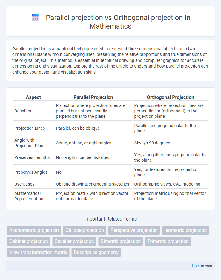
| Aspect | Parallel Projection | Orthogonal Projection |
|---|---|---|
| Definition | Projection where projection lines are parallel but not necessarily perpendicular to the plane | Projection where projection lines are perpendicular (orthogonal) to the projection plane |
| Projection Lines | Parallel, can be oblique | Parallel and perpendicular to the plane |
| Angle with Projection Plane | Acute, obtuse, or right angles | Always 90 degrees |
| Preserves Lengths | No, lengths can be distorted | Yes, along directions perpendicular to the plane |
| Preserves Angles | No | Yes, for features on the projection plane |
| Use Cases | Oblique drawing, engineering sketches | Orthographic views, CAD modeling |
| Mathematical Representation | Projection matrix with direction vector not normal to plane | Projection matrix using normal vector of the plane |
Introduction to Projection Methods in Graphics
Parallel projection maintains object scales regardless of depth, preserving relative dimensions in 3D to 2D representation, essential for technical drawings and CAD applications. Orthogonal projection, a specific type of parallel projection, uses perpendicular projection lines to the viewing plane, offering undistorted views ideal for architectural and engineering designs. Both methods facilitate accurate measurement and visualization without perspective distortion, crucial in computer graphics and visualization tasks requiring precise geometry representation.
Understanding Parallel Projection
Parallel projection preserves the relative proportions of objects by projecting points along parallel lines onto a projection plane, making it essential for technical drawings and engineering designs. Unlike perspective projection, it eliminates distortion caused by distance, ensuring accurate representation of spatial relationships and dimensions. Understanding parallel projection aids in differentiating between orthogonal projection, a type of parallel projection with projection lines perpendicular to the plane, and other projection methods used for visualization and modeling.
What is Orthogonal Projection?
Orthogonal projection is a type of parallel projection where the projection lines are perpendicular to the projection plane, ensuring that the dimensions along the axes remain true to scale. This method preserves the right angles and relative proportions of objects, making it widely used in engineering and architectural drawings for accurate representation. Unlike oblique projections, orthogonal projection eliminates distortion by maintaining consistent geometry regardless of the object's orientation.
Key Differences Between Parallel and Orthogonal Projections
Parallel projection and orthogonal projection are both techniques used in computer graphics and engineering drawings to represent three-dimensional objects on two-dimensional planes. Parallel projection projects points along parallel lines onto the projection plane, preserving relative proportions but potentially causing distortion in angles and lengths, while orthogonal projection, a subset of parallel projection, projects points perpendicularly to the plane, ensuring accurate measurements and true-scale representation of object dimensions. Key differences include angle of projection, with parallel projection allowing oblique angles and orthogonal strictly perpendicular, and the preservation of shape accuracy, which is higher in orthogonal projections due to its right-angle projection.
Mathematical Foundations of Projections
Orthogonal projection involves projecting a vector onto a subspace such that the error vector is orthogonal to the subspace, minimizing the Euclidean distance and preserving vector lengths. Parallel projection generalizes this concept by projecting vectors along parallel lines in a specified direction, not necessarily orthogonal, leading to skewed or oblique projections. The mathematical foundation of these projections relies on linear algebra concepts such as inner products, projection matrices, and subspace decompositions, where orthogonal projections use symmetric idempotent matrices and parallel projections can be represented by linear transformations defined by direction vectors.
Applications of Parallel Projection in Engineering and Design
Parallel projection, widely used in engineering drafting and computer-aided design (CAD), facilitates the creation of accurate 2D representations of 3D objects without perspective distortion, crucial for technical drawings and blueprints. Orthogonal projection, a subset of parallel projection, specifically projects points onto a plane along lines perpendicular to that plane, ensuring true-scale dimensions and angles are maintained, essential for mechanical part and architectural plans. Applications in mechanical engineering leverage parallel projection for detailed component analysis, while architectural design benefits from orthogonal views for planning and construction precision.
Uses of Orthogonal Projection in Visualization
Orthogonal projection is widely used in technical and engineering visualization to accurately represent three-dimensional objects on two-dimensional planes without distortion of angles or lengths, preserving true scale and shape. It is essential in CAD (Computer-Aided Design) for creating precise blueprints, architectural drawings, and mechanical parts where accurate measurements are critical. This projection type helps professionals analyze structural details and spatial relationships by providing a clear and dimensionally consistent view.
Advantages and Disadvantages: Parallel vs Orthogonal
Parallel projection preserves the relative proportions of objects, making it ideal for technical drawings and engineering designs where accurate measurements are crucial; however, it can lack depth perception compared to orthogonal projection. Orthogonal projection offers true scale representation on multiple axes and eliminates distortion caused by perspective, facilitating precise dimensioning and alignment in architectural plans, though it may appear less realistic and harder to interpret visually. While parallel projection simplifies the visualization of complex structures by keeping lines parallel, orthogonal projection excels in clarity and accuracy for manufacturing and CAD applications, but both techniques have limitations depending on the intended use and visual requirements.
Visual Representation and Example Comparisons
Parallel projection maintains parallelism of lines and scales objects uniformly without perspective distortion, ideal for engineering drawings like isometric views of machinery. Orthogonal projection, a subtype of parallel projection, projects points perpendicularly onto the projection plane, preserving true dimensions and shape angles, commonly used in architectural floor plans and CAD blueprints. Comparing both, orthogonal projection offers precise measurements with right-angle views, while general parallel projection allows angled views that reveal multiple sides simultaneously, enhancing spatial understanding.
Selecting the Right Projection Method for Your Project
Choosing between parallel projection and orthogonal projection depends on the project's precision and visual requirements. Parallel projection preserves scale without distortion, ideal for technical drawings and architectural plans where true dimensions are critical. Orthogonal projection, a subset of parallel projection with perpendicular projection lines, ensures accurate representation of shapes and is preferred for engineering designs demanding exact measurements.
Parallel projection Infographic