Parallel projection is a graphical technique used to represent three-dimensional objects in two dimensions, maintaining the relative proportions of the original object without perspective distortion. This method is especially valuable in technical and engineering drawings, where accurate measurements and clear visualization are essential. Discover how parallel projection can enhance your design process by exploring the detailed applications and variations in the following article.
Table of Comparison
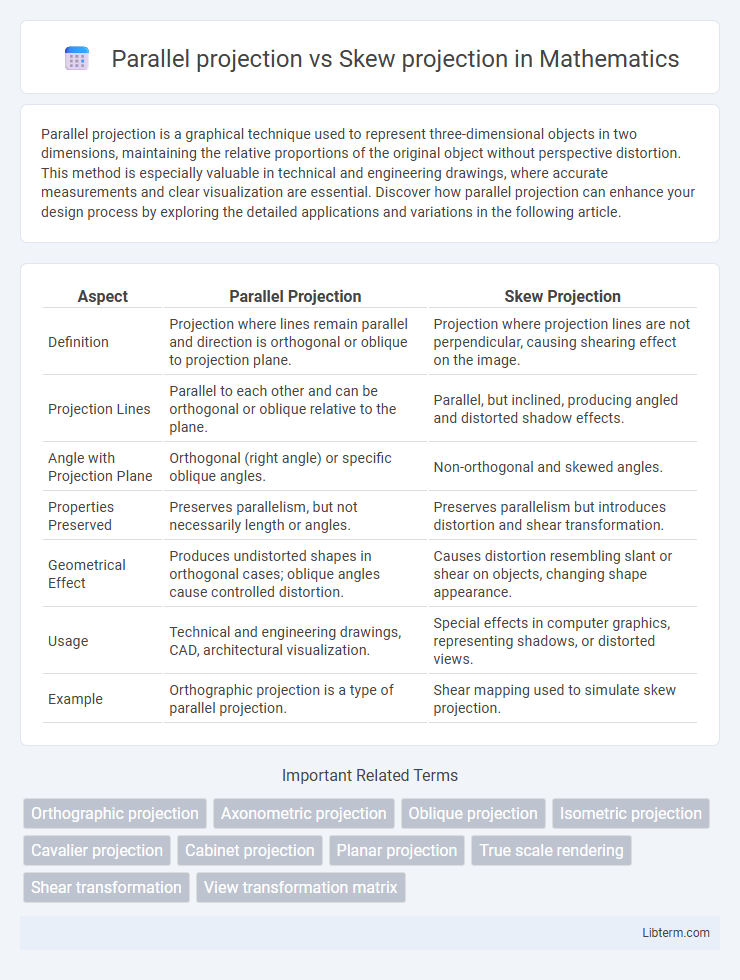
| Aspect | Parallel Projection | Skew Projection |
|---|---|---|
| Definition | Projection where lines remain parallel and direction is orthogonal or oblique to projection plane. | Projection where projection lines are not perpendicular, causing shearing effect on the image. |
| Projection Lines | Parallel to each other and can be orthogonal or oblique relative to the plane. | Parallel, but inclined, producing angled and distorted shadow effects. |
| Angle with Projection Plane | Orthogonal (right angle) or specific oblique angles. | Non-orthogonal and skewed angles. |
| Properties Preserved | Preserves parallelism, but not necessarily length or angles. | Preserves parallelism but introduces distortion and shear transformation. |
| Geometrical Effect | Produces undistorted shapes in orthogonal cases; oblique angles cause controlled distortion. | Causes distortion resembling slant or shear on objects, changing shape appearance. |
| Usage | Technical and engineering drawings, CAD, architectural visualization. | Special effects in computer graphics, representing shadows, or distorted views. |
| Example | Orthographic projection is a type of parallel projection. | Shear mapping used to simulate skew projection. |
Introduction to Parallel and Skew Projection
Parallel projection preserves the true dimensions of objects by projecting points along parallel lines, making it ideal for technical drawings and engineering designs where accurate measurements are crucial. Skew projection involves projecting points along lines that are neither parallel nor perpendicular to the projection plane, resulting in a distorted representation that can emphasize specific features or perspectives. Both projection methods are fundamental in computer graphics and geometric modeling for visualizing three-dimensional objects in two dimensions with varying levels of distortion and accuracy.
Fundamental Concepts of Projection in Graphics
Parallel projection preserves the relative proportions and angles of objects by projecting points along parallel lines onto the projection plane, enabling accurate dimensional measurements in technical graphics. Skew projection, a subset of parallel projection, involves projecting points along oblique lines, causing distortion where angles and lengths may not represent true dimensions. Understanding these fundamental concepts in graphics is critical for choosing the appropriate projection method for engineering drawings, architectural plans, and computer graphics rendering.
What is Parallel Projection?
Parallel projection is a geometric technique used in computer graphics to represent three-dimensional objects on a two-dimensional plane without perspective distortion, meaning all projectors remain parallel. This method preserves the relative proportions and scales of the object's dimensions, making it ideal for engineering and architectural drawings where accurate measurements are critical. Unlike skew projection, parallel projection maintains orthogonality between projection lines and the projection plane, ensuring true shape representation.
Types of Parallel Projection
Parallel projection includes orthographic and oblique types, each projecting objects onto a plane without perspective distortion. Orthographic projection features multiple views--front, top, and side--where projection lines are perpendicular to the projection plane. Oblique projection uses projection lines at an angle other than 90 degrees, combining one view in true scale with a skewed representation of depth.
What is Skew Projection?
Skew projection is a type of parallel projection where the projection lines are not perpendicular to the projection plane, causing the object to appear distorted or sheared. This method is used in computer graphics and technical drawing to represent depth while maintaining parallelism in one or more directions. Unlike orthographic projection, skew projection angles the projection rays to show the object's dimensions in a more visually dynamic or distorted way.
Key Differences Between Parallel and Skew Projection
Parallel projection maintains object dimensions and angles by projecting points along parallel lines, ensuring true size and shape representation in technical drawings. Skew projection distorts dimensions by projecting points along non-perpendicular lines, causing angles and lengths to appear skewed and less accurate. The key difference lies in parallel projection preserving orthogonality and scale, whereas skew projection alters geometric properties for visual effect or specific design purposes.
Advantages of Parallel Projection
Parallel projection offers the advantage of preserving the true dimensions and proportions of objects, making it ideal for technical drawings and engineering designs where accuracy is critical. It eliminates perspective distortion, ensuring that parallel lines remain parallel, which simplifies measurements and scaling. This projection method enhances clarity in visualizing complex structures by providing undistorted views essential for detailed analysis and manufacturing.
Benefits of Skew Projection
Skew projection offers unique benefits in visualizing objects by allowing the representation of shapes where dimensions are preserved along one axis and distorted along another, enhancing the perception of depth without altering parallelism. This technique enables clearer depiction of complex geometries by tilting the projection plane, which helps in simplifying the interpretation of spatial relationships compared to parallel projection. Skew projection is particularly advantageous in CAD and architectural design, where maintaining scale along one axis while providing a perspective effect improves both accuracy and visual comprehension.
Use Cases and Applications
Parallel projection is widely used in engineering and architectural drafting for creating accurate, scale-consistent technical drawings where measurements remain true without perspective distortion. Skew projection finds applications in computer graphics and visualization, particularly for rendering objects with a deliberate angular distortion to simulate specific viewpoints or artistic effects. Both projections serve distinct purposes: parallel projection ensures precise dimension representation, while skew projection enables creative visualization by manipulating object orientation.
Choosing the Right Projection Technique
Selecting the appropriate projection technique depends on the specific application requirements and visual clarity. Parallel projection preserves the true dimensions of objects, making it ideal for engineering drawings where accurate measurements are critical. Skew projection offers a more dynamic perspective by tilting the object, which enhances visual depth without converging lines but may distort measurements, making it suitable for artistic or conceptual designs.
Parallel projection Infographic