Axial load refers to the force applied along the longitudinal axis of a structural member, causing tension or compression. Proper understanding of axial load is crucial for designing safe and efficient buildings, bridges, and mechanical components. Explore this article to learn how axial load impacts structural integrity and how to calculate it accurately for your projects.
Table of Comparison
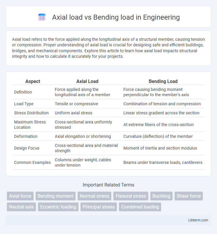
| Aspect | Axial Load | Bending Load |
|---|---|---|
| Definition | Force applied along the longitudinal axis of a member | Force causing bending moment perpendicular to the member's axis |
| Load Type | Tensile or compressive | Combination of tension and compression |
| Stress Distribution | Uniform axial stress | Linear stress gradient across the section |
| Maximum Stress Location | Cross-sectional area uniformly stressed | At extreme fibers of the cross-section |
| Deformation | Axial elongation or shortening | Curvature (deflection) of the member |
| Design Focus | Cross-sectional area and material strength | Moment of inertia and section modulus |
| Common Examples | Columns under weight, cables under tension | Beams under transverse loads, cantilevers |
Understanding Axial Load: Definition and Principles
Axial load refers to the force applied along the longitudinal axis of a structural member, causing tension or compression. This load type uniformly distributes stress across the cross-sectional area, influencing the member's ability to carry weight without deformation. Understanding axial load principles enables engineers to design structural elements that optimize strength and stability under direct pressure or pulling forces.
What is Bending Load? Key Concepts Explained
Bending load refers to a force applied perpendicular to the longitudinal axis of a structural element, causing it to bend or curve. Key concepts include the bending moment, which quantifies the internal moment resisting the bend, and the neutral axis, where the material experiences zero stress during bending. Understanding bending load is crucial for designing beams, bridges, and other structures to ensure they withstand these forces without failure.
Fundamental Differences: Axial Load vs Bending Load
Axial load refers to force applied along the longitudinal axis of a structural member, causing either tension or compression, while bending load induces moment forces that create tension on one side and compression on the other. The fundamental difference lies in stress distribution: axial load produces uniform normal stress across the cross-section, whereas bending load results in a linear variation of normal stress, with maximum values at the outer fibers. Understanding these distinctions is critical for structural analysis, design, and material selection to ensure safety and performance under different loading conditions.
Effects of Axial Load on Structural Elements
Axial load primarily induces compressive or tensile stresses along the length of structural elements, directly affecting their stability and load-bearing capacity. Excessive axial compression can lead to buckling, especially in slender columns, while axial tension can cause elongation and potential fracture if limits are exceeded. Understanding these effects is crucial for designing reinforcement and selecting appropriate materials to ensure structural integrity under combined loading conditions.
Impact of Bending Load on Structural Stability
Bending load induces tensile and compressive stresses within structural elements, significantly affecting their stability by causing deflection and potential buckling. Unlike axial loads that apply uniform compression or tension, bending loads create stress gradients leading to material fatigue and localized failures. Ensuring structural integrity under bending requires optimized cross-sectional design and reinforcement to resist moment-induced stresses.
Material Behavior Under Axial and Bending Loads
Materials under axial load primarily experience uniform stress along the length, resulting in either tensile or compressive deformation depending on the load direction. In contrast, bending loads induce a stress gradient across the material's cross-section, causing tension on one side and compression on the opposite side, which affects the material's yield and failure characteristics. Understanding these distinct stress distributions is crucial for predicting material behavior, durability, and structural integrity in engineering applications.
Common Applications of Axial and Bending Loads in Engineering
Axial loads commonly occur in structural columns, tension cables, and compression members where forces act along the longitudinal axis, ensuring stability in bridges and building frameworks. Bending loads are prevalent in beams, crane arms, and cantilever structures, causing deflection and stress due to transverse forces. Engineers design components like shafts and girders to withstand combined axial and bending stresses for safety and durability in mechanical and civil engineering applications.
Failure Modes: Axial Versus Bending Stresses
Axial loads produce uniform normal stresses along the cross-section, often leading to failure modes such as tensile cracking, buckling in compression, or yielding in ductile materials. Bending loads induce a stress gradient, causing tension on one side and compression on the opposite, which results in failure modes like tensile fracture on the tension side and compressive yielding or local buckling on the compression side. Understanding the distinct stress distributions in axial versus bending loads is crucial for predicting structural failure and designing components to resist specific load conditions.
Design Considerations for Axial and Bending Loads
Design considerations for axial loads prioritize ensuring the structural member can resist direct compressive or tensile forces without buckling or yielding, emphasizing material strength and cross-sectional area. For bending loads, the design focuses on the section modulus and moment of inertia to withstand bending moments and shear stresses, preventing excessive deflection or failure. Combining axial and bending loads requires evaluating interaction formulas to ensure safety and performance under combined stress conditions.
Testing Methods for Axial and Bending Loads in Structures
Testing methods for axial loads typically involve applying forces directly along the longitudinal axis of structural elements to measure compressive or tensile strength, using universal testing machines and strain gauges to record deformation and stress distribution. Bending load tests assess a structure's flexural capacity by applying transverse forces, often through three-point or four-point bending setups, capturing moment-curvature relationships with deflection sensors and load cells. Both tests utilize advanced instrumentation like digital image correlation and finite element analysis for precise stress-strain evaluation and failure mode identification in materials such as steel, concrete, and composites.
Axial load Infographic