Torsional load refers to the twisting force applied to an object, causing shear stress over its cross-section. Understanding torsional load is crucial for designing mechanical components that can withstand rotational forces without failure. Explore this article to learn how torsional load impacts various materials and structures and how you can apply this knowledge for safer, more efficient designs.
Table of Comparison
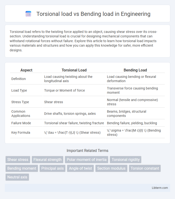
| Aspect | Torsional Load | Bending Load |
|---|---|---|
| Definition | Load causing twisting about the longitudinal axis | Load causing bending or flexural deformation |
| Load Type | Torque or Moment of force | Transverse force causing bending moment |
| Stress Type | Shear stress | Normal (tensile and compressive) stress |
| Common Applications | Drive shafts, torsion springs, axles | Beams, bridges, structural components |
| Failure Mode | Torsional shear failure, twisting fracture | Bending failure, yielding, buckling |
| Key Formula | \( \tau = \frac{T r}{J} \) (Shear stress) | \( \sigma = \frac{M c}{I} \) (Bending stress) |
Introduction to Torsional and Bending Loads
Torsional loads refer to forces that cause twisting around an axis, primarily affecting shafts, beams, and structural components subjected to torque. Bending loads involve forces producing bending moments that cause deflection and stress across the length of a beam or structural member. Understanding the distribution and magnitude of these loads is crucial for designing mechanical parts that withstand operational stresses without failure.
Defining Torsional Load: Concepts and Applications
Torsional load refers to the twisting force applied to an object, causing shear stress over the cross-section, commonly observed in shafts, drive axles, and propeller shafts. This load induces angular deformation and torsional shear stress, critical in designing mechanical components subjected to rotational forces. Understanding torsional load is essential for ensuring structural integrity and preventing failure in applications such as automotive drives, aerospace rotors, and industrial machinery.
Understanding Bending Load in Structural Analysis
Bending load in structural analysis refers to the force applied perpendicular to an object's longitudinal axis, causing it to bend or deform. This loading induces tensile stress on one side and compressive stress on the opposite side, critical in beam design and failure assessment. Understanding bending load effects is essential for calculating bending moments, shear forces, and deflection in structural elements to ensure safety and performance.
Key Differences Between Torsional and Bending Loads
Torsional loads induce twisting stresses around an object's longitudinal axis, resulting in shear stress distribution, while bending loads cause curvature with tensile and compressive stresses on opposite sides of the neutral axis. The critical difference lies in their stress types: torsion generates shear stress, whereas bending produces normal stress. Material resistance and structural design must account for these distinct stress patterns to ensure mechanical integrity under varying load conditions.
Material Behavior Under Torsional vs Bending Forces
Material behavior under torsional load involves shear stress distribution, causing twisting deformation, while bending load primarily induces normal stress with tension on one side and compression on the other. Torsional forces affect the material's shear modulus, leading to angular displacement, whereas bending stresses depend on the material's flexural strength and modulus of elasticity, resulting in curvature. Understanding these different stress responses is crucial for designing components subjected to combined loading to prevent failure.
Calculation Methods for Torsional and Bending Stresses
Torsional stress is calculated using the formula t = T*r / J, where T is the applied torque, r is the distance from the center, and J is the polar moment of inertia of the cross-section. Bending stress is determined by s = M*y / I, with M representing the bending moment, y the distance from the neutral axis, and I the moment of inertia of the beam's cross-section. Accurate calculation of these stresses ensures safe and efficient design in mechanical and structural engineering applications.
Real-world Examples: Torsional vs Bending Scenarios
Torsional loads occur in applications like drive shafts and helicopter rotors, where twisting forces induce shear stress along the component's axis, while bending loads dominate in beams and bridges subjected to vertical forces causing tension and compression on opposite sides. For instance, a car axle experiences torsion as the wheels apply torque, contrasting with a bridge beam that primarily bends under the weight of vehicles, resulting in flexural stress. Understanding these real-world scenarios helps engineers design materials and structures to effectively resist the specific stresses imposed by either torsion or bending.
Failure Modes Associated with Each Load Type
Torsional load primarily causes shear stress around the axis of the material, often leading to failure modes such as torsional fatigue, twisting fractures, and shear yielding. Bending load induces tensile and compressive stresses across the section, resulting in failure modes like bending fatigue, beam deflection leading to cracking, and tensile fracture on the convex side. Understanding the distinct stress distributions and associated failure patterns is crucial for designing components that can withstand specific mechanical demands.
Design Considerations for Torsional and Bending Loads
Design considerations for torsional and bending loads prioritize material selection, cross-sectional geometry, and stress distribution to prevent failure and ensure structural integrity. Torsional load design emphasizes shear stress capacity and resistance to twist, often requiring circular or tubular sections for uniform stress distribution. Bending load design focuses on flexural strength and stiffness, using beam theory to optimize moment of inertia and minimize deflection under applied loads.
Summary: Choosing Between Torsional and Bending Analysis
Torsional load analysis focuses on the effects of twisting forces causing shear stress, essential for components like shafts and couplings subjected to torque. Bending load analysis addresses stresses and deflections from perpendicular forces, critical for beams, bridges, and structural elements under load. Selecting between torsional and bending analysis depends on the dominant load type, geometry, and application, ensuring accurate stress assessment and structural integrity.
Torsional load Infographic