Flow nets are graphical tools used in groundwater engineering to analyze seepage through soil, depicting equipotential lines and flow lines to visualize water movement. The phreatic line represents the free surface of seepage where pore water pressure is atmospheric, crucial for assessing stability in earthen dams and levees. Explore the details in the rest of the article to understand how these concepts impact your geotechnical projects.
Table of Comparison
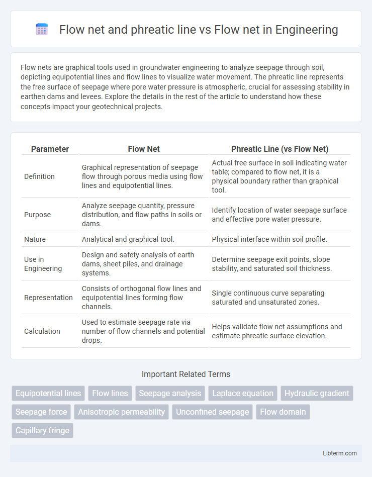
| Parameter | Flow Net | Phreatic Line (vs Flow Net) |
|---|---|---|
| Definition | Graphical representation of seepage flow through porous media using flow lines and equipotential lines. | Actual free surface in soil indicating water table; compared to flow net, it is a physical boundary rather than graphical tool. |
| Purpose | Analyze seepage quantity, pressure distribution, and flow paths in soils or dams. | Identify location of water seepage surface and effective pore water pressure. |
| Nature | Analytical and graphical tool. | Physical interface within soil profile. |
| Use in Engineering | Design and safety analysis of earth dams, sheet piles, and drainage systems. | Determine seepage exit points, slope stability, and saturated soil thickness. |
| Representation | Consists of orthogonal flow lines and equipotential lines forming flow channels. | Single continuous curve separating saturated and unsaturated zones. |
| Calculation | Used to estimate seepage rate via number of flow channels and potential drops. | Helps validate flow net assumptions and estimate phreatic surface elevation. |
Introduction to Flow Nets
Flow nets are graphical tools used in geotechnical engineering to analyze groundwater flow through soil, representing flow channels and equipotential lines that illustrate flow direction and pressure distribution. The phreatic line specifically demarcates the boundary between saturated and unsaturated zones in seepage problems, highlighting the free surface where pore water pressure equals atmospheric pressure. Understanding flow nets provides critical insights into seepage velocity, pressure heads, and potential slope stability issues in earth structures.
Fundamental Concepts of Flow Nets
Flow nets visualize two-dimensional steady-state groundwater flow through porous media by combining flow lines and equipotential lines, intersecting orthogonally to depict flow patterns and hydraulic gradients. The phreatic line represents the seepage face or free surface where pore water pressure equals atmospheric pressure, marking the upper boundary of saturated flow in flow nets. Fundamental concepts include Laplace's equation governing potential flow, boundary conditions defining impermeable and permeable surfaces, and the discrete flow channels formed between flow lines that quantify discharge and hydraulic head distribution.
Understanding the Phreatic Line
The phreatic line in soil mechanics represents the boundary within a flow net where pore water pressure equals atmospheric pressure, separating saturated from unsaturated zones. A flow net consists of flow lines and equipotential lines that map the flow of groundwater through soil, making the phreatic line a critical component for visualizing seepage patterns and calculating seepage quantities. Understanding the phreatic line helps engineers predict potential failure surfaces and design effective drainage systems in earth dams and levees.
Flow Nets: Construction and Applications
Flow nets are graphical tools used to analyze groundwater flow and seepage through soils by depicting flow lines and equipotential lines, which intersect perpendicularly to visualize velocity and pressure distribution. Constructing a flow net involves drawing a series of curvilinear flow channels bounded by flow lines and equipotential lines, allowing engineers to estimate seepage quantities, pore water pressures, and uplift forces in earth dams, retaining walls, and sluices. Applications of flow nets include designing effective drainage systems, assessing slope stability, and predicting the phreatic line, which represents the boundary between saturated and unsaturated zones in soil, crucial for evaluating seepage and structural safety.
Phreatic Line in Seepage Analysis
The phreatic line in seepage analysis represents the boundary between saturated and unsaturated zones within an earth dam or seepage system, marking the location where pore water pressure equals atmospheric pressure. Unlike the overall flow net, which consists of flow lines and equipotential lines illustrating the flow pattern and hydraulic gradients throughout the soil mass, the phreatic line specifically indicates the seepage face and helps predict seepage exit gradients, critical for assessing stability and potential erosion. Accurate identification of the phreatic line is essential in designing seepage control measures and ensuring the structural integrity of hydraulic structures.
Key Differences: Flow Net vs. Phreatic Line
Flow nets are graphical representations used to analyze seepage through soils by illustrating flow channels and equipotential lines, while the phreatic line specifically represents the seepage water table or free surface in a saturated soil mass. The key difference lies in that the flow net provides a complete mapping of flow paths and pressure heads, aiding in calculating seepage quantities and pressure distribution, whereas the phreatic line identifies the boundary between saturated and unsaturated zones within the soil. Flow nets encompass multiple flow lines and equipotential lines, whereas the phreatic line is a singular curve delineating seepage exit points and groundwater levels.
Advantages and Limitations of Flow Nets
Flow nets provide a visual representation of groundwater flow through soil and help estimate flow quantity, pore water pressure, and phreatic line position with simple construction methods based on equipotential and flow lines. Advantages include easy application for complex boundary conditions, no need for detailed soil parameters, and effectiveness in analyzing seepage under dams or embankments. Limitations involve reduced accuracy for anisotropic soils, inability to capture transient flow conditions, and dependency on user skill for precise line drawing and interpretation.
Practical Examples: Flow Nets vs. Phreatic Line
Flow nets graphically represent the flow of water through porous media, illustrating flow channels and equipotential lines that aid in analyzing seepage problems. The phreatic line, or the free surface separating saturated and unsaturated zones in earthen dams or embankments, is often delineated using flow nets to estimate seepage quantity and pressure distribution. Practical examples include determining seepage under dam foundations, where flow nets provide visual flow paths, while the phreatic line indicates potential failure zones due to saturation.
Common Mistakes in Flow Net and Phreatic Line Analysis
Common mistakes in flow net and phreatic line analysis include incorrect placement of flow lines and equipotential lines, leading to inaccurate seepage and pressure calculations. Misinterpreting the phreatic line's position often results from neglecting boundary conditions or soil permeability variations, causing errors in assessing groundwater levels and seepage forces. Ensuring correct node alignment and consistent flow domain discretization reduces errors in estimating pore water pressure and designing effective seepage control measures.
Conclusion: Selecting the Right Method for Seepage Studies
Flow nets provide a graphical solution for analyzing seepage through porous media, effectively illustrating flow paths and equipotential lines, while the phreatic line specifically denotes the free surface of seepage flow in earth dams and similar structures. Choosing between using a full flow net or focusing on the phreatic line depends on the complexity of the seepage problem; flow nets offer comprehensive insight for detailed seepage analysis, whereas identifying the phreatic line is crucial for assessing seepage exits and potential instability. For accurate seepage studies, flow nets should be employed for complete flow pattern visualization, and the phreatic line must be identified to evaluate water table fluctuations and structural safety.
Flow net and phreatic line Infographic