The slider-crank mechanism converts rotary motion into linear motion or vice versa, making it essential in engines and piston systems. Understanding its components, such as the crank, connecting rod, and slider, is crucial for analyzing mechanical efficiency and motion dynamics. Explore the detailed workings and applications of this mechanism in the rest of the article.
Table of Comparison
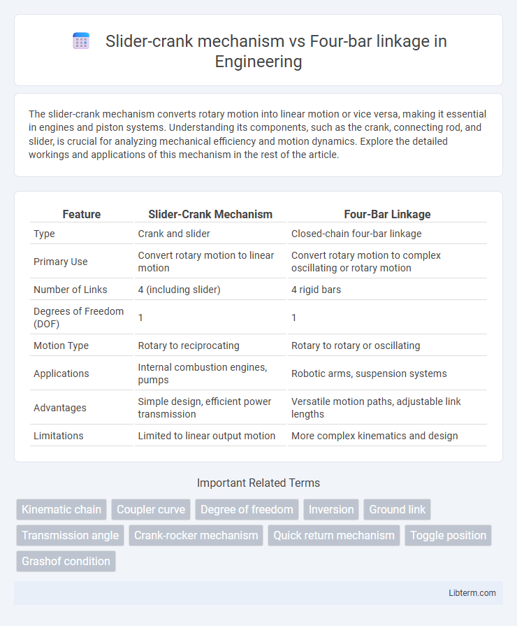
| Feature | Slider-Crank Mechanism | Four-Bar Linkage |
|---|---|---|
| Type | Crank and slider | Closed-chain four-bar linkage |
| Primary Use | Convert rotary motion to linear motion | Convert rotary motion to complex oscillating or rotary motion |
| Number of Links | 4 (including slider) | 4 rigid bars |
| Degrees of Freedom (DOF) | 1 | 1 |
| Motion Type | Rotary to reciprocating | Rotary to rotary or oscillating |
| Applications | Internal combustion engines, pumps | Robotic arms, suspension systems |
| Advantages | Simple design, efficient power transmission | Versatile motion paths, adjustable link lengths |
| Limitations | Limited to linear output motion | More complex kinematics and design |
Introduction to Slider-Crank Mechanism and Four-Bar Linkage
The slider-crank mechanism transforms rotary motion into linear motion, consisting of a crank, connecting rod, and slider, commonly used in engines and pumps. The four-bar linkage is a simpler planar mechanism composed of four rigid links connected by rotary joints, enabling complex motion paths in machinery and robotics. Both mechanisms serve fundamental roles in mechanical systems, with the slider-crank excelling in converting motion types and the four-bar linkage offering versatile motion control.
Fundamental Principles of Each Mechanism
The slider-crank mechanism converts rotary motion into linear motion using a crank, connecting rod, and a sliding component, relying on the geometric relationship between angular displacement and linear displacement. The four-bar linkage consists of four rigid bars connected in a loop by four revolute pairs, enabling complex planar motion through relative angular movement. Fundamental to the slider-crank is the transformation of reciprocating motion, while the four-bar linkage emphasizes controlled angular motion with varying transmission angles.
Components and Structural Differences
The slider-crank mechanism consists of a crank, connecting rod, and a sliding component, converting rotary motion into linear motion primarily used in engines and pumps. The four-bar linkage features four rigid links connected by revolute joints, enabling complex planar motion paths for applications like robotic arms and mechanical presses. Structurally, the slider-crank involves a sliding pair alongside revolute pairs, whereas the four-bar linkage exclusively uses four rotating pairs, distinguishing their mechanical mobility and functional versatility.
Motion Characteristics and Output Types
The slider-crank mechanism converts rotary motion into linear motion, producing a reciprocating output often used in engines and pumps. Four-bar linkages primarily generate complex planar motion, enabling a variety of output paths such as oscillatory, rotational, or coupler curves depending on link lengths and pivot positions. The slider-crank offers constrained, predictable linear displacement, while four-bar linkages provide versatile motion patterns suited for robotic arms and mechanical linkages.
Kinematic Analysis and Simplification
The slider-crank mechanism simplifies kinematic analysis by converting rotary motion into linear motion through a straightforward linkage consisting of a crank, connecting rod, and slider, allowing direct calculation of displacement, velocity, and acceleration. In contrast, the four-bar linkage, comprising four rigid links connected in a loop, requires more complex vector loop equations and angle analysis for precise motion determination, often involving nonlinear trigonometric relationships. The slider-crank's reduced degrees of freedom and well-defined input-output constraints make it more suited for applications demanding simpler kinematic models and easier dynamic synthesis compared to the more versatile but analytically intensive four-bar linkage.
Typical Engineering Applications
Slider-crank mechanisms are predominantly used in internal combustion engines, compressors, and pumps where converting rotary motion into reciprocating motion is essential. Four-bar linkages find extensive application in robotic arms, suspension systems, and mechanical presses, offering versatile motion control and force transmission. Both mechanisms are critical in mechanical engineering, with slider-crank focusing on linear displacement tasks and four-bar linkages on complex planar motion generation.
Advantages and Limitations Comparison
The slider-crank mechanism offers efficient conversion of rotary motion to linear motion, making it ideal for engines and pumps where precise pistoning is required. Its simple design results in high mechanical advantage and ease of maintenance, but it is limited by higher inertial forces and restricted motion paths compared to the versatile four-bar linkage. The four-bar linkage excels in generating complex planar motion with multiple degrees of freedom, providing greater flexibility at the cost of increased complexity and potential for greater wear in joints.
Efficiency and Performance Considerations
The slider-crank mechanism offers higher mechanical efficiency with direct linear motion conversion, minimizing energy losses in applications like internal combustion engines. Four-bar linkages provide more complex motion paths and greater flexibility but often experience increased friction and lower efficiency due to multiple pivot points. Optimizing performance involves selecting slider-crank systems for straightforward, high-efficiency tasks and four-bar linkages when nuanced motion control outweighs efficiency concerns.
Design Flexibility and Adaptability
Slider-crank mechanisms offer limited design flexibility due to their fixed linear and rotational motion paths, making them ideal for simple reciprocating tasks but less adaptable to complex movements. In contrast, four-bar linkages provide significant adaptability with their variable link lengths and pivot arrangements, enabling a wide range of output motions including elliptical and oscillating paths. Engineers often prefer four-bar linkages for custom motion design challenges where precise control over spatial paths and motion timing is required.
Selection Criteria: Choosing the Right Mechanism
When selecting between a slider-crank mechanism and a four-bar linkage, key criteria include the desired motion type and load capacity. Slider-crank mechanisms excel in converting rotary motion to linear motion with high force transmission, making them ideal for engines and compressors. Four-bar linkages offer versatile motion paths and smoother continuous rotation, preferred for applications requiring complex trajectory control and lower precision linear displacement.
Slider-crank mechanism Infographic