Bode plots graphically represent a system's frequency response by plotting magnitude and phase against frequency on logarithmic scales. They are essential tools for analyzing the stability and performance of control systems and designing filters. Discover how mastering Bode plots can improve your control system design by exploring the complete article.
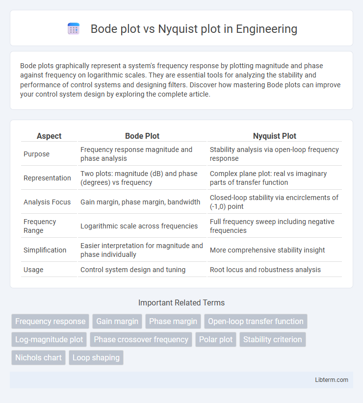
Table of Comparison
| Aspect | Bode Plot | Nyquist Plot |
|---|---|---|
| Purpose | Frequency response magnitude and phase analysis | Stability analysis via open-loop frequency response |
| Representation | Two plots: magnitude (dB) and phase (degrees) vs frequency | Complex plane plot: real vs imaginary parts of transfer function |
| Analysis Focus | Gain margin, phase margin, bandwidth | Closed-loop stability via encirclements of (-1,0) point |
| Frequency Range | Logarithmic scale across frequencies | Full frequency sweep including negative frequencies |
| Simplification | Easier interpretation for magnitude and phase individually | More comprehensive stability insight |
| Usage | Control system design and tuning | Root locus and robustness analysis |
Introduction to Frequency Response Analysis
Bode plots and Nyquist plots are fundamental tools in frequency response analysis for control systems and signal processing, representing system behavior across a range of frequencies. Bode plots display magnitude and phase separately on logarithmic scales, allowing clear visualization of gain margin and phase margin critical for stability assessment. Nyquist plots provide a complex plane representation of frequency response, enabling direct evaluation of encirclements around the critical point \(-1 + j0\) to determine closed-loop stability via the Nyquist stability criterion.
What is a Bode Plot?
A Bode plot is a graphical representation of a linear, time-invariant system's frequency response, displaying magnitude and phase versus frequency on logarithmic scales. It consists of two plots: the magnitude plot shows gain in decibels (dB), while the phase plot shows phase shift in degrees, both plotted against logarithmic frequency. Engineers use Bode plots to analyze stability margins, resonant peaks, and bandwidth in control systems and signal processing.
What is a Nyquist Plot?
A Nyquist plot is a graphical representation used in control systems and signal processing to analyze the frequency response of a linear time-invariant (LTI) system by plotting the complex-valued transfer function's amplitude and phase against frequency. It maps the real and imaginary parts of the system's open-loop transfer function on the complex plane to assess stability and gain margins. Unlike the Bode plot, which displays magnitude and phase separately against frequency, the Nyquist plot provides a comprehensive visualization of the system's frequency response in the complex plane.
Key Features of Bode Plots
Bode plots feature a logarithmic frequency axis with separate magnitude and phase plots, providing clear visualization of system gain and phase shift across frequencies. They are particularly useful in control systems and signal processing for evaluating stability margins and bandwidth. Unlike Nyquist plots, Bode plots distinctly separate gain and phase information, facilitating easier interpretation of frequency response characteristics.
Key Characteristics of Nyquist Plots
Nyquist plots display frequency response by mapping complex impedance or transfer function values on the complex plane, highlighting gain and phase stability margins crucial for control system analysis. They illustrate encirclements of the critical point \(-1 + 0j\), which directly indicate system stability according to the Nyquist stability criterion. Unlike Bode plots, Nyquist plots provide immediate visual insight into closed-loop stability through the path and encirclements in the Nyquist diagram.
Bode Plot vs Nyquist Plot: Core Differences
Bode plots display frequency response through separate magnitude and phase graphs, providing clear insight into gain margin and phase margin, which are essential for stability analysis in control systems. Nyquist plots represent complex frequency response in a single plot by tracing the real and imaginary parts of the system's transfer function over a frequency range, facilitating direct visualization of encirclements around critical points for assessing stability using the Nyquist criterion. Bode plots excel in design and tuning of feedback controllers, while Nyquist plots provide a comprehensive stability check, especially in systems with variable or uncertain parameters.
Applications of Bode Plots
Bode plots are widely used in control system design to analyze frequency response, stability margins, and gain crossover frequencies. They provide clear visualization of the magnitude and phase shift of a system's transfer function across a range of frequencies, aiding in the design of compensators and filters. Engineers rely on Bode plots for robust stability analysis and to predict system behavior under varying input signals.
Applications of Nyquist Plots
Nyquist plots are extensively used in control system analysis to determine system stability and robustness by mapping the complex frequency response of a system's open-loop transfer function. They provide critical insights into gain and phase margins, enabling engineers to predict system behavior under feedback conditions. Unlike Bode plots, Nyquist plots visually reveal encirclements of the critical point (-1,0), directly indicating closed-loop stability through the Nyquist stability criterion.
Advantages and Limitations: Bode vs Nyquist
Bode plots provide a clear frequency response representation with separate magnitude and phase plots, making it easier to analyze gain margin and phase margin for system stability in linear time-invariant systems. Nyquist plots offer a comprehensive view of system stability by depicting the complex frequency response directly, enabling stability assessments with the Nyquist stability criterion, especially in feedback control systems. However, Bode plots can be less intuitive for complex poles and zeros interactions, while Nyquist plots may become difficult to interpret for high-order systems due to their intricate contour encirclements.
Choosing Between Bode and Nyquist Plots
Bode plots provide clear frequency response visualization with separate magnitude and phase graphs, making them ideal for control system design and stability margin assessment in linear time-invariant systems. Nyquist plots offer a comprehensive view of system stability by mapping complex frequency response in the complex plane, preferred for evaluating closed-loop stability through the Nyquist criterion. Choosing between them depends on the need for detailed frequency response characteristics (Bode) versus direct stability analysis in the complex domain (Nyquist).
Bode plot Infographic