A ladder circuit is an electrical network composed of repeating units arranged in a structure resembling a ladder, often used in filters and impedance matching. These circuits provide precise control over voltage and current distribution, making them essential in signal processing and electronic measurement. Discover how understanding ladder circuits can improve your design and troubleshooting skills by reading the full article.
Table of Comparison
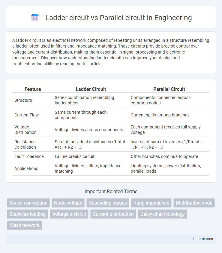
| Feature | Ladder Circuit | Parallel Circuit |
|---|---|---|
| Structure | Series combination resembling ladder steps | Components connected across common nodes |
| Current Flow | Same current through each component | Current splits among branches |
| Voltage Distribution | Voltage divides across components | Each component receives full supply voltage |
| Resistance Calculation | Sum of individual resistances (Rtotal = R1 + R2 + ...) | Inverse of sum of inverses (1/Rtotal = 1/R1 + 1/R2 + ...) |
| Fault Tolerance | Failure breaks circuit | Other branches continue to operate |
| Applications | Voltage dividers, filters, impedance matching | Lighting systems, power distribution, parallel loads |
Introduction to Ladder and Parallel Circuits
Ladder circuits consist of repeated units resembling the rungs of a ladder, primarily used in applications like digital logic and signal processing for their simplicity and predictable behavior. Parallel circuits feature components connected alongside each other, allowing multiple current paths and maintaining the same voltage across all components, commonly utilized in household wiring and lighting systems. Understanding the structural and functional differences between ladder and parallel circuits is essential for selecting the appropriate circuit design in electrical engineering and electronics projects.
Defining Ladder Circuit: Structure and Function
A ladder circuit consists of a series of resistors forming two parallel lines connected by multiple "rungs," resembling a ladder's structure, commonly used in digital-to-analog converters (DACs) and signal processing. Each rung provides a voltage division, allowing precise control and predictable current flow through the circuit branches. The unique configuration enables simplified analysis and consistent performance, making ladder circuits essential in applications requiring accurate voltage references and impedance matching.
Understanding Parallel Circuit: Key Characteristics
Parallel circuits feature multiple paths for electric current, enabling components to operate independently while maintaining the same voltage across each branch. They provide improved reliability because a failure in one path does not interrupt the entire circuit, unlike ladder circuits where current flows sequentially. Parallel circuits are commonly used in household wiring to ensure consistent voltage and prevent complete system failure.
Core Differences Between Ladder and Parallel Circuits
Ladder circuits consist of series-connected components arranged in a step-like structure, optimizing voltage division and current control across each rung. Parallel circuits feature multiple branches connected across the same voltage source, allowing independent current flow through each path with uniform voltage. The core difference lies in the current flow management: ladder circuits distribute current sequentially, while parallel circuits provide simultaneous and independent current paths.
Advantages of Ladder Circuits
Ladder circuits offer precise voltage and current outputs, making them ideal for digital-to-analog converter applications where accuracy is critical. Their structured, repetitive design simplifies troubleshooting and enhances scalability compared to parallel circuits, which can suffer from complex interconnections and voltage drops. The inherent stability and ease of implementation in ladder circuits promote consistent performance in measurement and control systems.
Benefits of Parallel Circuits
Parallel circuits offer significant benefits including consistent voltage across all components, which ensures uniform performance in devices connected to the circuit. They provide enhanced reliability because if one branch fails, the other branches continue to function without interruption. Parallel circuits also allow easy addition or removal of components without impacting the overall circuit operation, making them ideal for complex electrical systems.
Typical Applications of Ladder Circuits
Ladder circuits are commonly utilized in digital-to-analog converters (DACs) and signal processing applications due to their precise voltage division and easy scalability. They are widely employed in telecommunications and audio equipment for generating reference voltages and filtering signals. Unlike parallel circuits, ladder circuits provide accurate and stable performance in systems requiring precise and linear voltage outputs.
Common Uses of Parallel Circuits
Parallel circuits are commonly used in household electrical wiring to ensure that each appliance operates independently without affecting others, providing consistent voltage across all devices. They are also essential in battery systems for electric vehicles and renewable energy setups, allowing multiple cells to share the load and increase current capacity. This configuration improves reliability and maintenance, as individual components can be disconnected without disrupting the entire circuit.
Considerations for Choosing Between Ladder and Parallel Circuits
When selecting between ladder and parallel circuits, consider factors such as complexity, voltage distribution, and fault tolerance. Ladder circuits provide simpler voltage control and are often used in applications requiring sequential operation, while parallel circuits ensure consistent voltage across components and allow independent operation. Evaluate the specific requirements of the system, including load uniformity and maintenance ease, to determine the optimal configuration.
Conclusion: Ladder Circuit vs Parallel Circuit Comparison
Ladder circuits provide precise voltage division and improved signal integrity, making them ideal for resistor networks and digital-to-analog converters, whereas parallel circuits offer straightforward current distribution suitable for powering multiple loads independently. The ladder design minimizes interference and ensures stable node voltages, while parallel circuits excel in maintaining consistent voltage across components with variable current demands. Choosing between ladder and parallel circuits depends on the application's need for voltage accuracy versus flexibility in load management.
Ladder circuit Infographic