Cut-off frequency defines the point where a system's output signal starts to attenuate significantly, marking the boundary between passband and stopband in filters and circuits. Understanding this frequency is crucial for designing and optimizing electronic filters, ensuring signals remain within desired frequency ranges. Explore the rest of the article to deepen your understanding of cut-off frequency and its practical applications.
Table of Comparison
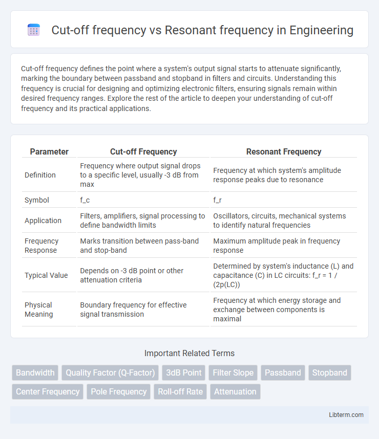
| Parameter | Cut-off Frequency | Resonant Frequency |
|---|---|---|
| Definition | Frequency where output signal drops to a specific level, usually -3 dB from max | Frequency at which system's amplitude response peaks due to resonance |
| Symbol | f_c | f_r |
| Application | Filters, amplifiers, signal processing to define bandwidth limits | Oscillators, circuits, mechanical systems to identify natural frequencies |
| Frequency Response | Marks transition between pass-band and stop-band | Maximum amplitude peak in frequency response |
| Typical Value | Depends on -3 dB point or other attenuation criteria | Determined by system's inductance (L) and capacitance (C) in LC circuits: f_r = 1 / (2p(LC)) |
| Physical Meaning | Boundary frequency for effective signal transmission | Frequency at which energy storage and exchange between components is maximal |
Introduction to Cut-off Frequency and Resonant Frequency
Cut-off frequency marks the point in a system where the output signal power drops to half its maximum value, defining the bandwidth limit of filters and communication channels. Resonant frequency is the specific frequency at which a system naturally oscillates with maximum amplitude due to constructive interference of energy. Understanding both frequencies is crucial in designing circuits, filters, and mechanical systems for optimal performance and signal integrity.
Defining Cut-off Frequency: Concepts and Applications
Cut-off frequency defines the threshold at which a system's output power drops to half its maximum value, typically marking the boundary between passband and stopband in filters and circuits. It plays a critical role in signal processing by determining the frequency range where a device effectively operates, such as in low-pass, high-pass, and band-pass filters. Unlike resonant frequency, which indicates the frequency at which a system naturally oscillates with maximum amplitude, cut-off frequency is essential for design criteria that control bandwidth and filter attenuation.
Understanding Resonant Frequency in Circuits
Resonant frequency in circuits is the specific frequency at which the inductive reactance and capacitive reactance are equal in magnitude but opposite in phase, causing the circuit to oscillate with maximum amplitude. This frequency is defined by the formula \( f_0 = \frac{1}{2\pi\sqrt{LC}} \), where L represents the inductance and C the capacitance in the circuit. Understanding resonant frequency is critical for designing tuned circuits, filters, and oscillators, as it determines the frequency at which energy transfer is most efficient and signal response is maximized.
Mathematical Formulas for Cut-off and Resonant Frequencies
Cut-off frequency (f_c) is calculated using the formula \( f_c = \frac{1}{2\pi RC} \) for an RC circuit, where R is resistance and C is capacitance. Resonant frequency (f_r) in an LC circuit is given by \( f_r = \frac{1}{2\pi \sqrt{LC}} \), where L represents inductance and C capacitance. These formulas quantify the distinct operational points where cut-off frequency marks the boundary between pass and stop bands, while resonant frequency identifies the peak response in frequency-selective circuits.
Physical Interpretation: How Frequencies Affect Signal Behavior
Cut-off frequency defines the boundary in a system where signal attenuation begins, marking the transition between passband and stopband behavior, while resonant frequency corresponds to the natural oscillation rate where energy storage and transfer between reactive components amplify signal response. At the cut-off frequency, signals experience a significant reduction in amplitude, impacting the effective bandwidth and signal clarity, whereas at resonant frequency, constructive interference leads to peak amplitude and phase shifts that enhance signal transmission or energy transfer. Understanding the interplay between cut-off and resonant frequencies is essential for optimizing filter design, signal processing, and tuning applications in communication and electronic circuits.
Key Differences Between Cut-off Frequency and Resonant Frequency
Cut-off frequency refers to the boundary in a system's frequency response where the output signal starts to significantly attenuate, commonly seen in filters and waveguides. Resonant frequency is the specific frequency at which a system naturally oscillates with maximum amplitude due to constructive interference or energy storage, typical in circuits like LC oscillators or mechanical systems. Key differences include that cut-off frequency marks a threshold for attenuation, whereas resonant frequency represents peak energy transfer or oscillation, and cut-off frequency is often associated with filter characteristics while resonant frequency relates to energy resonance phenomena.
Practical Examples in Electronic Circuits
Cut-off frequency in electronic circuits marks the point where the output signal power drops to half its maximum value, commonly seen in low-pass filters that block frequencies above this threshold, such as the 3 kHz cut-off in audio crossover networks. Resonant frequency occurs when inductive and capacitive reactances in circuits, like LC tank circuits in radio transmitters, cancel each other out, producing maximum voltage or current. Practical differences are evident in tone control circuits where cut-off frequency defines bandwidth limits, whereas resonant frequency determines the peak response for tuning radios or oscillators.
Importance in Filter Design: Low-pass, High-pass, and Band-pass
Cut-off frequency defines the threshold where a filter significantly attenuates input signals, crucial for shaping signal bandwidth in low-pass, high-pass, and band-pass filters. Resonant frequency identifies the point at which a filter exhibits maximum amplitude response or energy storage, directly impacting the selectivity and sharpness in band-pass filter design. Precise control of both frequencies ensures optimal filtering performance, minimizing signal distortion and maximizing clarity in electronic and communication systems.
Measurement Techniques for Frequency Parameters
Measurement techniques for cut-off frequency primarily involve analyzing the amplitude response of a system using network analyzers or frequency sweeps to identify the point where the signal drops to a specified level, typically -3 dB. Resonant frequency measurement techniques rely on detecting the peak response in amplitude or impedance using devices such as impedance analyzers, vector network analyzers, or modal analysis tools to accurately capture the resonance point. Precision in frequency parameter measurement is enhanced by employing methods like swept-sine testing, ring-down analysis, and phase response monitoring to distinguish between cut-off and resonant frequencies effectively.
Summary: Choosing the Right Frequency for Your Application
Cut-off frequency defines the boundary at which a system begins to attenuate signals, serving as a critical parameter for filters and frequency response analysis. Resonant frequency represents the frequency at which a system naturally oscillates with maximum amplitude, crucial for maximizing energy transfer in applications like antennas and mechanical systems. Selecting the right frequency between cut-off and resonant depends on achieving balance between signal integrity and system efficiency based on the specific application requirements.
Cut-off frequency Infographic