A ladder circuit is an electrical network composed of repeating units of resistors or reactive components arranged in a pattern resembling a ladder, commonly used in filters and impedance matching. It offers precise control over signal characteristics and frequency response, making it essential for applications in telecommunications and signal processing. Explore the rest of this article to understand how a ladder circuit can optimize your electronic designs.
Table of Comparison
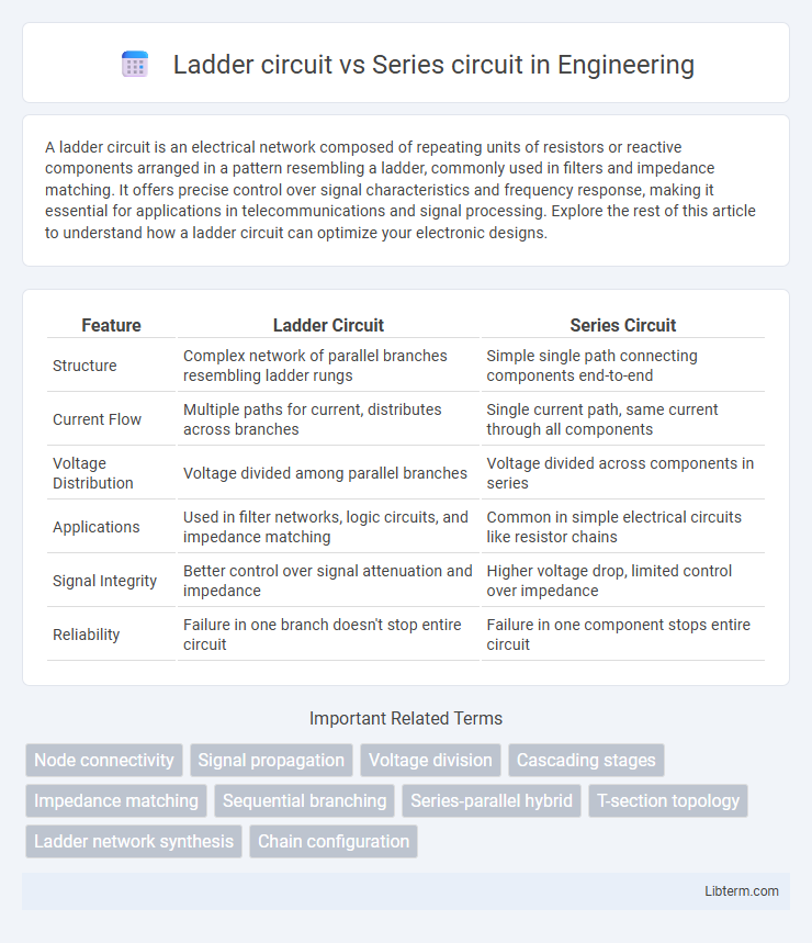
| Feature | Ladder Circuit | Series Circuit |
|---|---|---|
| Structure | Complex network of parallel branches resembling ladder rungs | Simple single path connecting components end-to-end |
| Current Flow | Multiple paths for current, distributes across branches | Single current path, same current through all components |
| Voltage Distribution | Voltage divided among parallel branches | Voltage divided across components in series |
| Applications | Used in filter networks, logic circuits, and impedance matching | Common in simple electrical circuits like resistor chains |
| Signal Integrity | Better control over signal attenuation and impedance | Higher voltage drop, limited control over impedance |
| Reliability | Failure in one branch doesn't stop entire circuit | Failure in one component stops entire circuit |
Introduction to Ladder and Series Circuits
Ladder circuits consist of repeating units of series and parallel components that form a structure resembling a ladder, commonly used in electrical engineering for filter and network design. Series circuits feature components connected end-to-end, creating a single path for current flow, fundamental for understanding voltage drops and resistance. Both circuit types are essential for analyzing electrical behavior, with ladder circuits enabling complex impedance configurations while series circuits simplify current flow analysis.
Basic Definitions: Ladder Circuit vs Series Circuit
A Ladder circuit is an electrical network composed of repeating units resembling the rungs and sides of a ladder, often used in filters and impedance matching. A Series circuit connects components end-to-end such that current flows through each component sequentially, with the same current throughout. While series circuits emphasize continuous current flow through components, ladder circuits focus on combining series and parallel elements to achieve specific electrical properties.
Key Components and Structure Comparison
A ladder circuit features repeating units of series and parallel components arranged in a stepwise pattern, enhancing signal processing and impedance matching, while a series circuit consists of components connected end-to-end in a single path, which influences voltage distribution and current flow uniformly across each element. Key components in ladder circuits typically include resistors, capacitors, or inductors configured to create precise filtering or voltage division, whereas series circuits primarily rely on resistors or other passive elements to control current flow. Structurally, ladder circuits resemble a "runged" framework optimizing stability and performance in communication systems, while series circuits maintain simplicity and straightforward connectivity suited for current regulation and basic electrical pathways.
Electrical Flow: How Current Travels
In a ladder circuit, electrical current flows through multiple parallel branches interconnected by series elements, allowing current to split and recombine, maintaining a consistent voltage across parallel components. In contrast, a series circuit features a single path for electrical flow, where current remains constant through each component sequentially, and voltage drops accumulate across the series elements. The ladder circuit design supports complex current distribution with varying branch currents, while the series circuit enforces uniform current but varying voltage levels across each resistor or device.
Voltage Distribution Differences
In a ladder circuit, voltage distribution occurs through a network of parallel branches resembling a ladder, allowing voltage drops to be divided more evenly across each branch based on their impedance. Series circuits exhibit a linear voltage drop where the total voltage is the sum of individual voltage drops across each component, directly proportional to their resistance. Ladder circuits provide more controlled and customizable voltage distribution compared to the linear, cumulative voltage drop characteristic of series circuits.
Applications in Electrical Engineering
Ladder circuits are widely used in digital-to-analog converters (DACs) and signal processing due to their precision and predictable voltage division. Series circuits find extensive applications in controlling the current flow in electrical devices such as incandescent bulbs, resistors in heating elements, and sensing circuits. Electrical engineers leverage ladder circuits for accurate voltage scaling in measurement instruments, while series circuits are fundamental in ensuring uniform current distribution across components.
Pros and Cons of Ladder Circuits
Ladder circuits offer precise impedance matching and reduced signal loss, making them ideal for RF filter applications and signal processing. They provide improved stability and frequency response compared to simple series circuits but involve increased design complexity and higher component count, which can raise manufacturing costs. Maintenance challenges arise from their interconnected design, requiring careful troubleshooting compared to straightforward series circuits.
Pros and Cons of Series Circuits
Series circuits offer a simple design with components connected end-to-end, resulting in uniform current flow through each element, which makes them easy to analyze and troubleshoot. However, a major disadvantage is that if one component fails or is disconnected, the entire circuit is interrupted, causing all devices to lose power. The voltage divides across components, potentially leading to insufficient voltage for individual devices when multiple resistive elements are present.
Practical Examples and Use Cases
Ladder circuits, commonly used in industrial control systems such as programmable logic controllers (PLCs), allow easy troubleshooting and modification by representing electrical control logic visually. Series circuits, widely applied in simple circuit designs like string lights and fuse protection, ensure a single path for current flow, making voltage drop and current consistency critical factors. Practical use of ladder circuits includes automated manufacturing processes, while series circuits are fundamental in devices requiring sequential operation or basic electrical continuity.
Choosing the Right Circuit for Your Project
Ladder circuits provide a structured approach ideal for sequential switching applications and relay logic in industrial control, offering ease of troubleshooting and scalability. Series circuits are simpler, delivering straightforward current flow through components, best suited for low-complexity tasks where consistent current is required. Selecting between ladder and series circuits depends on project needs for complexity, control precision, and ease of maintenance.
Ladder circuit Infographic