Torsion occurs when an object twists due to applied torque, causing shear stress within the material. Understanding torsion is crucial for designing shafts, beams, and mechanical components to prevent failure and ensure safety. Explore this article to learn how torsion affects structures and how to manage its impact effectively.
Table of Comparison
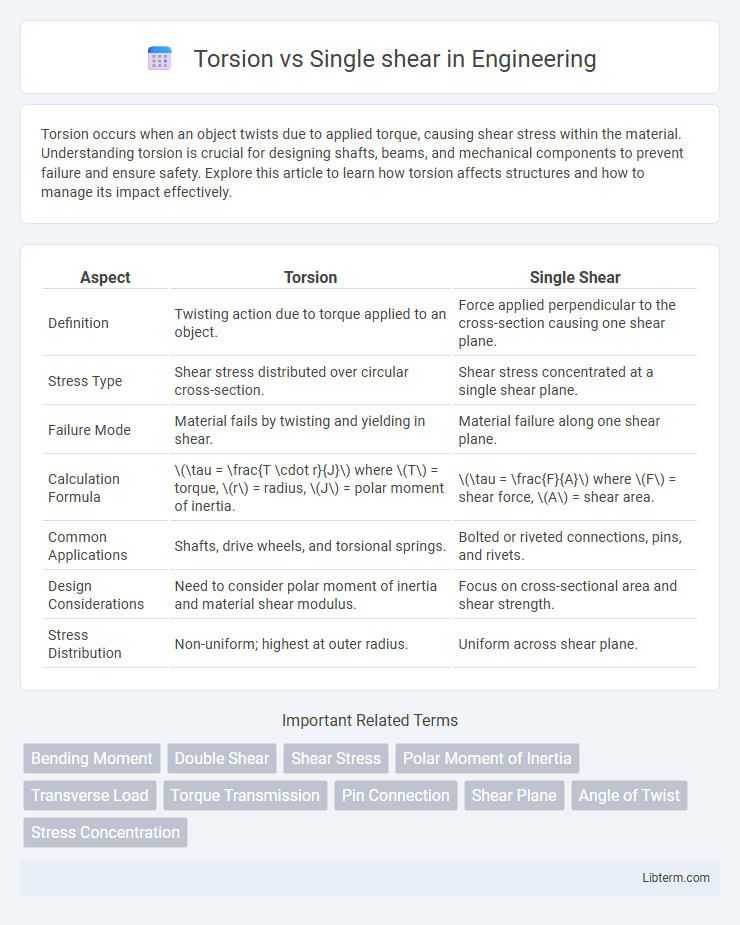
| Aspect | Torsion | Single Shear |
|---|---|---|
| Definition | Twisting action due to torque applied to an object. | Force applied perpendicular to the cross-section causing one shear plane. |
| Stress Type | Shear stress distributed over circular cross-section. | Shear stress concentrated at a single shear plane. |
| Failure Mode | Material fails by twisting and yielding in shear. | Material failure along one shear plane. |
| Calculation Formula | \(\tau = \frac{T \cdot r}{J}\) where \(T\) = torque, \(r\) = radius, \(J\) = polar moment of inertia. | \(\tau = \frac{F}{A}\) where \(F\) = shear force, \(A\) = shear area. |
| Common Applications | Shafts, drive wheels, and torsional springs. | Bolted or riveted connections, pins, and rivets. |
| Design Considerations | Need to consider polar moment of inertia and material shear modulus. | Focus on cross-sectional area and shear strength. |
| Stress Distribution | Non-uniform; highest at outer radius. | Uniform across shear plane. |
Introduction to Torsion and Single Shear
Torsion is a mechanical stress that occurs when a structural element, such as a shaft or beam, is subjected to a twisting force causing rotational deformation around its longitudinal axis. Single shear, on the other hand, involves a force applied parallel to the surface of a material, resulting in a shear stress that attempts to slide one section of the material past another along a single plane. Understanding the differences between torsion and single shear is crucial in engineering design to ensure components can withstand specific load conditions without failure.
Fundamental Concepts: Torsion Explained
Torsion refers to the twisting of an object due to an applied torque or rotational force, causing shear stress across the material's cross-section. Single shear occurs when a material is subjected to a force that causes it to slide along a single plane, resulting in shear stress concentrated on that plane. Unlike single shear, torsion generates a varying distribution of shear stress around the entire cross-section, making its analysis crucial for designing shafts and structural components subjected to twisting loads.
Understanding Single Shear Mechanism
Single shear mechanism involves a material or fastener experiencing a force that acts parallel to the cross-sectional area, causing the object to fail along a single plane. This shear force distribution results in one distinct shear surface where the load is transferred and resisted, commonly seen in pins, bolts, or rivets under load. Understanding single shear requires analyzing the magnitude of the force relative to the cross-sectional area to ensure the component maintains structural integrity without slipping or fracturing.
Key Differences Between Torsion and Single Shear
Torsion involves twisting a material or structural element about its longitudinal axis, generating shear stress distributed across the cross-section, while single shear refers to a force applied perpendicular to a material's axis, causing a single plane of failure. In torsion, shear stresses vary radially and result in angular deformation, whereas single shear produces uniform shear stress concentrated along the shear plane. Key differences include the nature of the applied forces, stress distribution, and resulting deformation patterns in materials subjected to torsion versus single shear loading.
Applications of Torsion in Engineering
Torsion is widely applied in engineering to analyze shafts, axles, and drive components subjected to twisting forces, ensuring structural integrity in mechanical systems. Common applications include power transmission shafts in automotive and aerospace industries, where torsional stress influences design for durability and performance. Single shear primarily evaluates forces on fasteners and connections, differing from torsion's focus on rotational stress in components.
Common Uses of Single Shear Joints
Single shear joints are prevalently used in structural engineering for connecting load-bearing members such as beams and columns where the applied force acts perpendicular to the fastener axis. These joints provide efficient load transfer in applications like mechanical linkages, bolted connections in steel frameworks, and welded plate joints commonly found in construction and machinery assembly. Their design simplicity and reliability make them ideal for fastening components subjected to shear forces without the complexity of torsional stress considerations.
Failure Modes: Torsion vs Single Shear
Torsion failure occurs primarily due to excessive shear stress causing twisting deformation, leading to cracks or fractures along the material's length. Single shear failure happens when the applied force causes the material to fail along a single plane, typically resulting in a clean shear surface or a cut through the cross-section. Understanding these distinct failure modes is critical for designing components subject to rotational loads versus linear shear forces.
Design Considerations and Safety Factors
Design considerations for torsion emphasize resistance to twisting moments, requiring materials and cross-sections with high shear strength and rigidity, often using circular or tubular shapes to distribute torsional stresses uniformly. Single shear design focuses on the capacity of a fastener or joint to withstand shear forces acting parallel to the axis, necessitating the selection of appropriate bolt sizes and materials to prevent failure under load. Safety factors are critical in both, with torsion typically demanding higher factors due to complex stress distributions, while single shear factors depend on material ductility and connection reliability to ensure structural integrity under variable loads.
Material Selection for Torsion and Single Shear
Material selection for torsion emphasizes high shear strength and toughness to resist twisting stresses, commonly utilizing alloy steels, aluminum alloys, and composites. In single shear applications, materials with high tensile strength and ductility, such as carbon steels and stainless steels, are preferred to withstand shear forces along the failure plane. Both conditions demand careful consideration of fatigue resistance and corrosion properties to ensure durability under cyclic loading and environmental exposure.
Summary: Choosing Between Torsion and Single Shear
Torsion and single shear are critical mechanical stress types used in engineering to evaluate material performance under twisting and cutting forces, respectively. Torsion deals with torque causing rotational deformation, fundamental in shafts and rotary components, while single shear involves a force applied perpendicular to the axis, common in rivets and bolts under load. Selecting between torsion and single shear depends on the application's loading conditions, component geometry, and failure criteria to ensure structural integrity and optimal design.
Torsion Infographic