Rack and pinion systems convert rotational motion into linear motion with high precision and efficiency, commonly used in steering mechanisms and machinery. Understanding the mechanics and applications of rack and pinion helps improve control and accuracy in various engineering projects. Discover how rack and pinion technology can enhance your designs by reading the rest of this article.
Table of Comparison
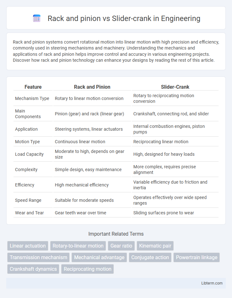
| Feature | Rack and Pinion | Slider-Crank |
|---|---|---|
| Mechanism Type | Rotary to linear motion conversion | Rotary to reciprocating motion conversion |
| Main Components | Pinion (gear) and rack (linear gear) | Crankshaft, connecting rod, and slider |
| Application | Steering systems, linear actuators | Internal combustion engines, piston pumps |
| Motion Type | Continuous linear motion | Reciprocating linear motion |
| Load Capacity | Moderate to high, depends on gear size | High, designed for heavy loads |
| Complexity | Simple design, easy maintenance | More complex, requires precise alignment |
| Efficiency | High mechanical efficiency | Variable efficiency due to friction and inertia |
| Speed Range | Suitable for moderate speeds | Operates effectively over wide speed ranges |
| Wear and Tear | Gear teeth wear over time | Sliding surfaces prone to wear |
Introduction to Rack and Pinion and Slider-Crank Mechanisms
Rack and pinion and slider-crank mechanisms convert rotational motion into linear motion, serving diverse engineering applications. The rack and pinion features a circular gear (pinion) engaging with a linear toothed rack, enabling precise linear displacement control in steering systems and CNC machinery. The slider-crank mechanism consists of a crank connected to a slider via a connecting rod, commonly used in internal combustion engines and piston pumps to create reciprocating motion.
Basic Working Principles
Rack and pinion systems convert rotational motion into linear motion through a circular gear (pinion) engaging with a linear gear (rack), enabling precise control of movement along a straight path. Slider-crank mechanisms transform rotational motion into reciprocating linear motion via a crankshaft connected to a slider through a connecting rod, commonly used in engines and pumps. The rack and pinion provides continuous linear motion, while the slider-crank delivers oscillatory or back-and-forth movement.
Key Mechanical Components
Rack and pinion mechanisms feature a linear gear (rack) engaging with a circular gear (pinion) to convert rotational motion into linear motion, crucial for steering systems and precise positioning. Slider-crank assemblies consist of a crank, connecting rod, and slider, transforming rotational motion into reciprocating motion widely used in engines and compressors. The key mechanical components in rack and pinion emphasize gear teeth and meshing accuracy, whereas slider-crank components focus on pivot joints and linkage rigidity for smooth motion transmission.
Motion Conversion: Linear to Rotary
Rack and pinion systems convert linear motion into rotary motion by meshing a linear gear (rack) with a circular gear (pinion), allowing precise and smooth rotational output from linear input. Slider-crank mechanisms transform linear motion into rotary motion through a connecting rod and crankshaft arrangement, enabling complex motion paths with varying angular velocities. Both systems efficiently perform motion conversion, but rack and pinion provides direct linear-to-rotary translation while slider-crank mechanisms offer versatility in motion dynamics and force transmission.
Efficiency and Power Transmission
Rack and pinion mechanisms offer high efficiency and precision in converting rotational motion to linear motion, making them ideal for low-friction power transmission in steering systems and CNC machines. Slider-crank mechanisms typically experience more energy loss due to friction and complex joint interactions, resulting in lower mechanical efficiency during power transmission in engines and compressors. The rack and pinion's direct engagement between gear teeth reduces backlash and energy loss, whereas slider-crank systems involve sliding contact and reciprocating motion that increase wear and reduce overall efficiency.
Applications in Industry
Rack and pinion systems are widely used in automotive steering mechanisms and industrial automation for precise linear motion control, offering high efficiency and durability. Slider-crank mechanisms find significant applications in internal combustion engines, compressors, and mechanical presses where rotational motion converts to reciprocating motion. Both systems are essential in machinery design but differ in motion type and mechanical advantage tailored to specific industrial requirements.
Advantages and Disadvantages
Rack and pinion mechanisms offer high precision and smooth linear motion ideal for steering systems but can suffer from wear and require regular maintenance due to gear tooth contact. Slider-crank linkages provide efficient conversion between rotary and linear motion, commonly used in engines for power transmission, yet they experience higher friction and stress at joints, limiting durability. Both systems have specific advantages in mechanical design but must be chosen based on application requirements like load, accuracy, and maintenance capabilities.
Durability and Maintenance Requirements
Rack and pinion mechanisms typically offer higher durability due to fewer moving components subject to wear compared to slider-crank systems, which involve sliding contacts prone to friction and degradation. Maintenance requirements for rack and pinion setups are generally lower, as they mostly need periodic lubrication and inspection, while slider-crank mechanisms demand more frequent adjustments and replacement of worn seals or bearings to maintain efficiency. Selecting between these systems depends on the application's load conditions and desired lifespan, with rack and pinion preferred for systems emphasizing longevity and minimal upkeep.
Suitability for Specific Engineering Tasks
Rack and pinion mechanisms excel in linear motion applications requiring precise positioning, such as steering systems and CNC machinery, due to their high accuracy and direct conversion of rotational to linear motion. Slider-crank mechanisms suit tasks involving oscillatory or reciprocating motion, commonly found in internal combustion engines and compressors, offering robust performance in transferring rotary motion to linear reciprocation. Engineering task suitability depends on motion type, required precision, load capacity, and mechanical complexity, making rack and pinion preferable for controlled linear displacement and slider-cranks ideal for repetitive linear motion with varying stroke lengths.
Summary and Comparative Analysis
Rack and pinion mechanisms convert rotational motion into linear motion through a gear and toothed rack interaction, offering precise control and straightforward design, widely used in steering systems. Slider-crank mechanisms transform rotational motion into reciprocating linear motion via a crank and connecting rod attached to a sliding component, commonly found in engines and pumps. Compared to slider-crank, rack and pinion systems provide smoother linear output with less vibration but handle lower force loads, while slider-cranks excel in converting high torque to strong reciprocating motion at the cost of increased mechanical complexity and wear.
Rack and pinion Infographic