Shear load refers to a force that causes parts of a material to slide past each other in opposite directions, often leading to deformation or failure along a plane. Understanding how shear load impacts structural elements is essential for designing safe and durable engineering systems. Explore this article to learn more about shear load effects and how they influence your design decisions.
Table of Comparison
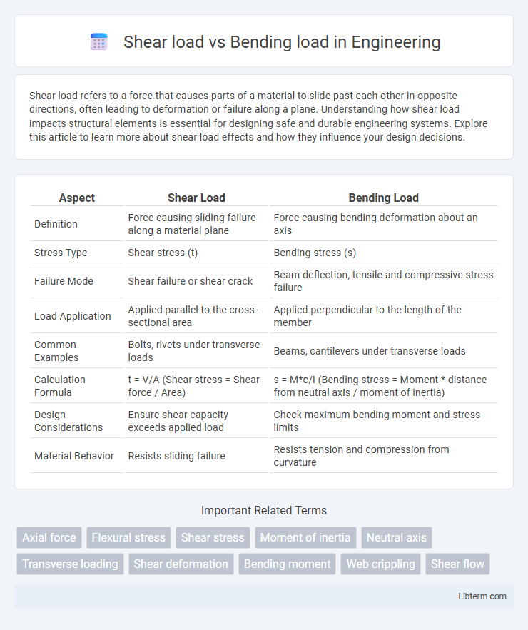
| Aspect | Shear Load | Bending Load |
|---|---|---|
| Definition | Force causing sliding failure along a material plane | Force causing bending deformation about an axis |
| Stress Type | Shear stress (t) | Bending stress (s) |
| Failure Mode | Shear failure or shear crack | Beam deflection, tensile and compressive stress failure |
| Load Application | Applied parallel to the cross-sectional area | Applied perpendicular to the length of the member |
| Common Examples | Bolts, rivets under transverse loads | Beams, cantilevers under transverse loads |
| Calculation Formula | t = V/A (Shear stress = Shear force / Area) | s = M*c/I (Bending stress = Moment * distance from neutral axis / moment of inertia) |
| Design Considerations | Ensure shear capacity exceeds applied load | Check maximum bending moment and stress limits |
| Material Behavior | Resists sliding failure | Resists tension and compression from curvature |
Introduction to Shear Load and Bending Load
Shear load occurs when forces act parallel or tangential to a material's surface, causing layers to slide against each other, typically experienced in beams and bolts. Bending load involves forces that create tension on one side and compression on the opposite side of a structural element, leading to deflection and potential failure in beams and girders. Understanding the distinct stress distributions and failure modes in shear and bending loads is critical for designing safe and efficient structural components.
Defining Shear Load
Shear load refers to the force that causes two adjacent parts of a material to slide past one another in opposite directions, typically acting parallel to the surface. It is critical in assessing structural elements such as beams, where the material experiences a shearing stress that tends to cause deformation along the cross-sectional plane. In contrast, bending load generates tension and compression within a beam, causing it to curve rather than slide internally.
Understanding Bending Load
Bending load refers to a force applied perpendicular to the longitudinal axis of a structural member, causing it to bend and experience tension on one side and compression on the other. This load induces internal stresses that vary linearly across the cross-section, critical for designing beams and other flexural components. Understanding bending load is essential for calculating moment distribution, deflection, and ensuring structural stability under applied forces.
Key Differences Between Shear and Bending Loads
Shear load causes internal forces that act parallel to the cross-section of a structural element, leading to sliding failure between material layers, while bending load induces internal moments that create tension and compression across the cross-section, resulting in bending deformation. Shear stresses are typically highest along the neutral axis, whereas bending stresses peak at the outer fibers of the beam's cross-section. Design calculations for shear loads prioritize shear stress distribution, whereas bending load analysis focuses on moment-curvature relationships and flexural strength.
Common Applications of Shear and Bending Loads
Shear loads are commonly encountered in applications such as bolt connections, riveted joints, and cutting tools where forces act parallel to the surface, causing material layers to slide over each other. Bending loads are prevalent in beams, bridges, and cantilevers where forces cause deformation by bending and induce tension and compression across the cross-section. Understanding the behavior of materials under shear and bending loads is crucial for designing safe and efficient structural components in civil, mechanical, and aerospace engineering.
Effects on Structural Integrity
Shear load causes internal sliding forces along a section of a material, often leading to shear failure or cracks that compromise the structural integrity. Bending load induces tensile and compressive stresses on opposite sides of a structural element, potentially resulting in deformation, buckling, or fracture. Understanding the distinct impacts of shear and bending loads is essential for designing resilient structures capable of withstanding combined stress conditions.
Failure Modes: Shear vs. Bending
Shear load primarily causes material failure through shear stress, resulting in sliding or tearing along a plane parallel to the applied force, commonly seen in bolts and beams under transverse loading. Bending load induces tensile and compressive stresses across the cross-section, leading to failure modes such as tensile cracking on the tension side and compressive crushing on the compression side. Understanding the distinct failure modes under shear and bending is crucial for designing structural components to prevent catastrophic fractures and ensure durability.
Material Selection for Different Loads
Material selection for shear load involves choosing materials with high shear strength and toughness, such as steel alloys or composites designed to resist deformation and failure under lateral forces. For bending loads, materials with high flexural strength and modulus of elasticity, like aluminum alloys or fiber-reinforced plastics, are preferred to withstand tensile and compressive stresses without cracking. Understanding the specific load type is critical to optimizing performance and durability by selecting materials that align with the mechanical properties required for either shear resistance or bending stiffness.
Design Considerations for Shear and Bending
Design considerations for shear load focus on selecting materials and cross-sectional shapes that resist sliding failures and shear stress concentrations, often employing web stiffeners and shear reinforcements in beams. Bending load design prioritizes maximizing the moment of inertia through flange thickness and shape adjustments to prevent bending stress and deflection, with attention to neutral axis location and compressive/tensile stress distribution. Both designs require safety factors aligned with load conditions and structural use, ensuring adequate resistance to combined shear and bending effects in beams and structural members.
Conclusion: Choosing the Right Load Analysis
Selecting the appropriate load analysis depends on the structural application and load conditions, where shear load analysis is critical for elements subjected to forces parallel to their cross-section, ensuring resistance to shear failure. Bending load analysis is essential for components experiencing moments causing curvature, focusing on stress distribution and deflection control. Accurate differentiation between shear and bending loads optimizes design safety, structural integrity, and material efficiency in engineering projects.
Shear load Infographic