The principal axis refers to the main line of symmetry or the direction along which certain physical properties, such as moments of inertia or optical behavior, are aligned in an object or system. Understanding the principal axis can significantly simplify complex calculations in physics and engineering by reducing multi-dimensional problems into one-dimensional analysis. Explore this article to discover how mastering the principal axis concept enhances your problem-solving skills in various scientific fields.
Table of Comparison
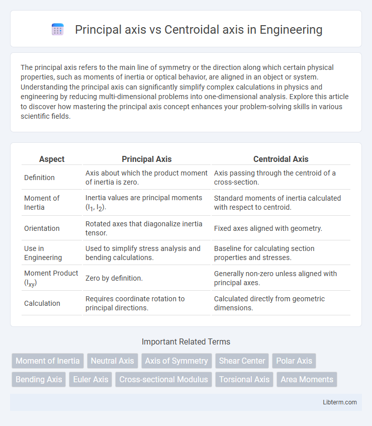
| Aspect | Principal Axis | Centroidal Axis |
|---|---|---|
| Definition | Axis about which the product moment of inertia is zero. | Axis passing through the centroid of a cross-section. |
| Moment of Inertia | Inertia values are principal moments (I1, I2). | Standard moments of inertia calculated with respect to centroid. |
| Orientation | Rotated axes that diagonalize inertia tensor. | Fixed axes aligned with geometry. |
| Use in Engineering | Used to simplify stress analysis and bending calculations. | Baseline for calculating section properties and stresses. |
| Moment Product (Ixy) | Zero by definition. | Generally non-zero unless aligned with principal axes. |
| Calculation | Requires coordinate rotation to principal directions. | Calculated directly from geometric dimensions. |
Introduction to Principal and Centroidal Axes
Principal axes are the orthogonal lines passing through an object's centroid where the moments of inertia reach their extreme values, simplifying stress and deformation analysis in structural engineering. Centroidal axes intersect at the centroid, the geometric center of an area, and serve as the reference for calculating moments of inertia and other cross-sectional properties. Understanding the distinction between principal and centroidal axes optimizes the design and analysis of beams, shafts, and other structural elements by accurately predicting their bending and torsional behaviors.
Defining the Principal Axis
The principal axis refers to the orientation in a cross-sectional area where the moment of inertia reaches its maximum or minimum value, crucial for analyzing bending and torsion in structural elements. It is defined by the eigenvectors of the inertia tensor, representing directions along which shear stresses vanish and bending moments act purely. Understanding and locating the principal axis ensures accurate stress distribution assessment and optimal design in mechanical and civil engineering applications.
Understanding the Centroidal Axis
The centroidal axis is an axis that passes through the centroid, which is the geometric center of a shape or cross-section, and is crucial in structural analysis for calculating moments of inertia and stress distribution. Unlike the principal axis, which represents orientations where the product of inertia is zero and the section's moments of inertia are minimized or maximized, the centroidal axis provides a reference point for analyzing bending and torsion about the shape's center. Understanding the centroidal axis enables engineers to accurately predict deformation and design more efficient structural elements by considering how loads interact with the shape's inherent geometry.
Mathematical Formulation of Both Axes
The principal axis is mathematically determined by diagonalizing the inertia tensor, yielding eigenvalues and eigenvectors that define directions where the product of inertia is zero, optimizing rotational properties. The centroidal axis passes through the centroid of the area or mass distribution, computed by setting the first moments of area equal to zero, ensuring balance of forces. Both axes involve integration of spatial coordinates weighted by area or mass density, but the principal axis aligns with natural principal moments of inertia, while the centroidal axis centers the coordinate system.
Key Differences Between Principal and Centroidal Axes
Principal axes are the axes at which the moment of inertia tensor is diagonalized, representing directions of pure bending without twisting; centroidal axes, on the other hand, pass through the centroid of the area or volume, serving as the reference for calculating moments of inertia and section properties. A key difference lies in orientation: principal axes correspond to the directions where product of inertia is zero, while centroidal axes are not necessarily aligned with principal directions if the shape is asymmetric. Structural analysis relies on principal axes to simplify stress and strain calculations, whereas centroidal axes provide geometric centering for determining overall balance and dimensions.
Physical Significance in Engineering Applications
Principal axes represent directions in a cross-section where the moment of inertia reaches extreme values, crucial for analyzing bending and torsion in structural elements. Centroidal axes pass through the centroid of the area, serving as reference axes for calculating moments of inertia and simplifying stress distribution analysis. Understanding the distinction aids engineers in accurately predicting deflections, stresses, and stability in beams and rotating shafts.
Calculation Methods for Principal and Centroidal Axes
Calculation of the principal axis involves determining the orientation where the moments of inertia reach their maximum and minimum values, typically by solving the eigenvalue problem of the inertia tensor. The centroidal axis calculation starts with locating the centroid of the cross-section using the first moments of area and then recalculating the moments of inertia about this centroidal axis. Both methods employ integral calculus for complex shapes, while formulas and coordinate transformations simplify the process for standard geometric sections.
Common Examples in Structural Elements
Principal axes and centroidal axes are critical in analyzing structural elements like beams and columns to predict bending behavior and stress distribution accurately. For instance, in I-beams, the centroidal axis passes through the geometric center of the cross-section, while principal axes are oriented to minimize product of inertia, often aligning with the web and flange directions for maximum strength. Rectangular and circular columns primarily use centroidal axes for simplicity in design, but principal axes become essential in irregular or unsymmetrical cross-sections to determine torsional effects and principal moments of inertia.
Practical Implications in Design and Analysis
The principal axis represents the orientation where the moment of inertia is maximized or minimized, crucial for analyzing bending stresses in structural elements. The centroidal axis passes through the geometric center of a section, serving as the reference for calculating moments of inertia and shear force distributions. Understanding the difference impacts design optimization, as aligning loads and supports along principal axes reduces stress concentrations and improves structural stability.
Conclusion: Choosing the Right Axis for Analysis
Selecting the appropriate axis for structural analysis depends on the specific application and accuracy requirements. The principal axis, defined by the directions of maximum and minimum moments of inertia, provides critical insights for stress and deformation calculations in non-uniform or complex cross-sections. The centroidal axis simplifies analysis by aligning with the geometric center, ideal for symmetrical sections where bending stresses are uniformly distributed.
Principal axis Infographic