A bridge circuit is an electrical configuration designed to measure unknown components such as resistances, capacitances, or inductances by balancing two legs of a circuit. It operates on the principle of null detection, where the output voltage becomes zero when the bridge is balanced, allowing for precise measurements. Explore the rest of this article to understand how a bridge circuit can optimize your electrical testing and diagnostics.
Table of Comparison
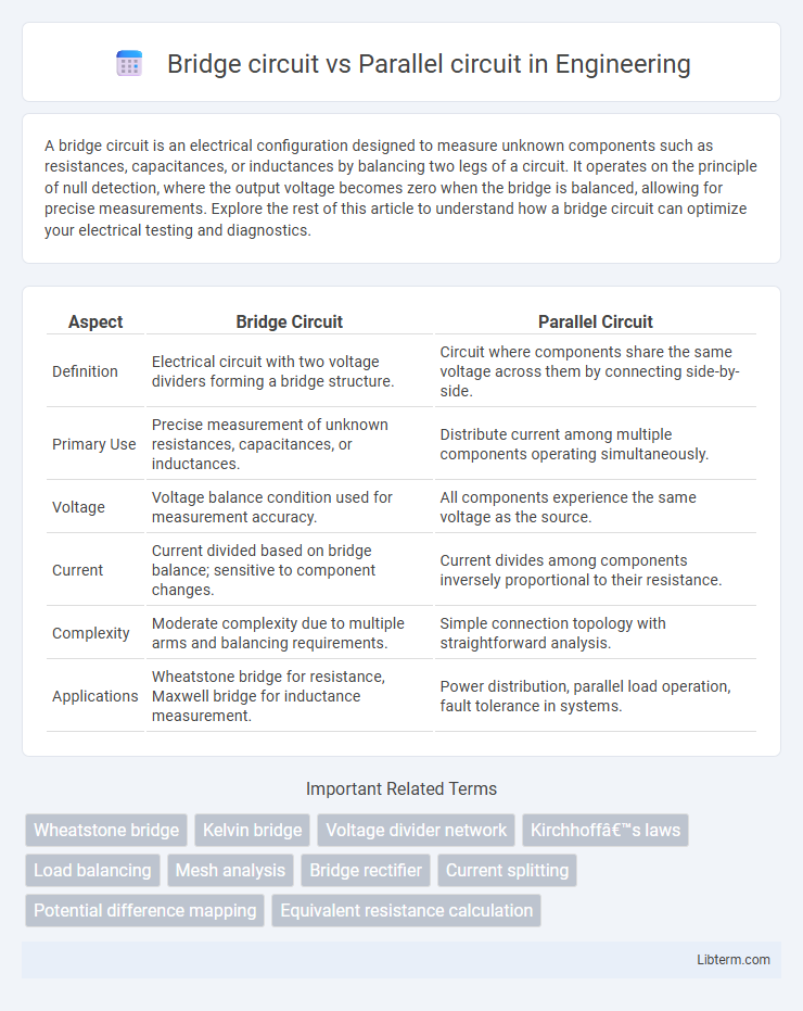
| Aspect | Bridge Circuit | Parallel Circuit |
|---|---|---|
| Definition | Electrical circuit with two voltage dividers forming a bridge structure. | Circuit where components share the same voltage across them by connecting side-by-side. |
| Primary Use | Precise measurement of unknown resistances, capacitances, or inductances. | Distribute current among multiple components operating simultaneously. |
| Voltage | Voltage balance condition used for measurement accuracy. | All components experience the same voltage as the source. |
| Current | Current divided based on bridge balance; sensitive to component changes. | Current divides among components inversely proportional to their resistance. |
| Complexity | Moderate complexity due to multiple arms and balancing requirements. | Simple connection topology with straightforward analysis. |
| Applications | Wheatstone bridge for resistance, Maxwell bridge for inductance measurement. | Power distribution, parallel load operation, fault tolerance in systems. |
Introduction to Bridge Circuits and Parallel Circuits
Bridge circuits are electrical networks designed to measure unknown components by balancing two legs of a circuit, often used in precise resistance or impedance measurement applications. Parallel circuits have components connected across the same voltage source, allowing multiple paths for current flow and ensuring consistent voltage across all elements. Bridge circuits leverage the principle of balancing voltage drops for accurate measurements, while parallel circuits simplify current distribution and maintain voltage uniformity.
Basic Structure of Bridge Circuits
Bridge circuits consist of four resistive arms arranged in a diamond shape, with a voltage source connected across two opposite junctions and a galvanometer or detector connected across the other two. This configuration allows precise measurement of unknown components by balancing the bridge, where no current flows through the detector. In contrast, parallel circuits have components connected across the same two nodes, sharing voltage but drawing independent currents, lacking the comparative measurement feature inherent in bridge circuits.
Basic Structure of Parallel Circuits
Parallel circuits consist of multiple components connected across the same voltage source, allowing each branch to operate independently with identical voltage. The basic structure features nodes where current divides and recombines, ensuring that the total current is the sum of individual branch currents. Unlike bridge circuits, which have a more complex arrangement for precise measurement and balancing, parallel circuits provide straightforward current distribution and simplified fault isolation.
Working Principle: Bridge Circuit
The working principle of a bridge circuit is based on the balanced condition of the two voltage dividers formed by four resistive arms, allowing precise measurement of unknown components by nullifying the voltage across the bridge. When the ratio of resistances in one voltage divider equals the ratio in the other, the bridge reaches a balanced state and the output voltage becomes zero, indicating a condition of equilibrium. This method enhances sensitivity and accuracy in applications such as strain gauge sensors, impedance measurement, and Wheatstone bridge configurations.
Working Principle: Parallel Circuit
A parallel circuit operates by dividing the electric current into multiple paths, allowing each component to receive the full voltage independently. Each branch in a parallel circuit has its own separate path to the power source, ensuring that if one branch fails, the others continue to function without interruption. This working principle contrasts with a bridge circuit, where the voltage and current distribution depend on the balance of resistances in the network.
Key Differences Between Bridge and Parallel Circuits
A bridge circuit consists of four resistors configured in a diamond shape, allowing precise measurement of unknown resistance through balance detection, unlike a parallel circuit where components share common voltage across multiple branches. In parallel circuits, current divides among branches inversely proportional to their resistance, while in bridge circuits, current flow depends on the balance condition, making them suitable for sensor and instrumentation applications. Key differences include the bridge circuit's ability to provide null measurement for accurate sensing versus the parallel circuit's simple current division and voltage distribution properties.
Common Applications of Bridge Circuits
Bridge circuits are widely used in precision measurement applications such as strain gauge sensors, temperature measurement with thermistors, and impedance matching in audio equipment due to their ability to accurately detect small changes in resistance. Common bridge configurations like the Wheatstone bridge facilitate high-sensitivity resistance measurements in industrial and laboratory settings. Parallel circuits, by contrast, are typically employed in power distribution and lighting systems where uniform voltage supply to multiple components is required.
Common Applications of Parallel Circuits
Parallel circuits are widely used in household electrical wiring because they allow multiple devices to operate independently with a consistent voltage across each branch, ensuring reliable performance for lights, appliances, and outlets. In automotive electrical systems, parallel circuits enable separate components such as headlights, radios, and dashboard instruments to function simultaneously without affecting each other. Industrial machinery often employs parallel circuits to maintain stable operation of multiple motors or sensors, enhancing safety and efficiency in complex systems.
Advantages and Disadvantages of Bridge Circuits
Bridge circuits offer precise measurement capabilities, especially in detecting unknown component values such as resistance, capacitance, and inductance, with enhanced sensitivity and accuracy compared to parallel circuits. They provide improved noise rejection and can balance voltages across components, reducing measurement errors, but require careful calibration and can be more complex to design and implement. Despite their complexity, bridge circuits are advantageous for high-precision applications, whereas parallel circuits are simpler but less effective in fine measurements.
Advantages and Disadvantages of Parallel Circuits
Parallel circuits offer the advantage of independent operation of each component, ensuring that if one branch fails, the others continue functioning without interruption. They provide consistent voltage across all components, which is essential for devices requiring stable voltage levels. However, parallel circuits can consume more power and are more complex to design and troubleshoot due to the multiple current paths.
Bridge circuit Infographic