Potential transformers accurately step down high voltages to safe, manageable levels for measurement and protection in electrical power systems. They provide precise voltage signals to metering devices and relays, ensuring system reliability and safety. Discover more about how potential transformers enhance your electrical infrastructure by reading the rest of the article.
Table of Comparison
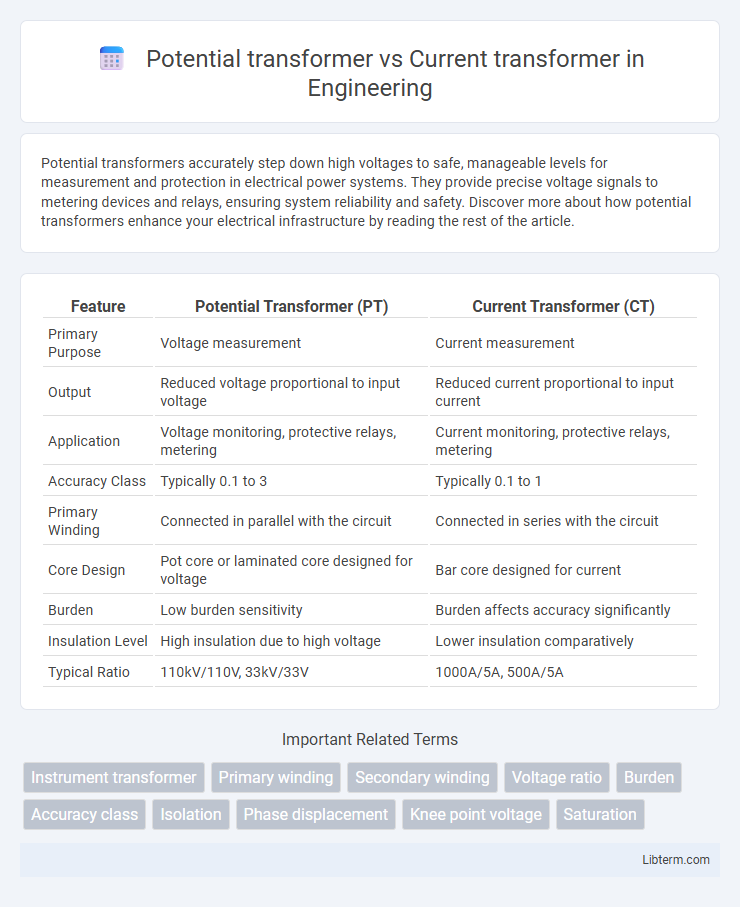
| Feature | Potential Transformer (PT) | Current Transformer (CT) |
|---|---|---|
| Primary Purpose | Voltage measurement | Current measurement |
| Output | Reduced voltage proportional to input voltage | Reduced current proportional to input current |
| Application | Voltage monitoring, protective relays, metering | Current monitoring, protective relays, metering |
| Accuracy Class | Typically 0.1 to 3 | Typically 0.1 to 1 |
| Primary Winding | Connected in parallel with the circuit | Connected in series with the circuit |
| Core Design | Pot core or laminated core designed for voltage | Bar core designed for current |
| Burden | Low burden sensitivity | Burden affects accuracy significantly |
| Insulation Level | High insulation due to high voltage | Lower insulation comparatively |
| Typical Ratio | 110kV/110V, 33kV/33V | 1000A/5A, 500A/5A |
Introduction to Instrument Transformers
Instrument transformers, including Potential Transformers (PTs) and Current Transformers (CTs), play a crucial role in electrical power systems by scaling high voltages and currents to manageable levels for metering, protection, and control equipment. Potential Transformers precisely step down high voltage signals to standardized lower voltages for accurate voltage measurement and monitoring, while Current Transformers reduce high current levels to standardized, safe values for current measurement and relay operation. Both types ensure isolation between high voltage power circuits and sensitive instrumentation, enhancing safety and measurement accuracy in electrical networks.
What is a Potential Transformer (PT)?
A Potential Transformer (PT) is an electrical device used to step down high voltages to standardized low voltages for measurement and protection purposes in power systems. It ensures accurate voltage scaling with minimal power loss and maintains electrical isolation between high-voltage circuits and measuring instruments. PTs are essential for safely monitoring high-voltage equipment and facilitating the operation of relays and meters.
What is a Current Transformer (CT)?
A Current Transformer (CT) is an electromagnetic device used to measure high alternating currents by producing a reduced current accurately proportional to the current in the primary circuit, enabling safe monitoring and metering. CTs are essential in power systems for protection relays and instrumentation, isolating measurement devices from high voltage circuits. Unlike Potential Transformers (PTs), which measure voltage, CTs specifically handle current measurement and provide standard output currents, typically 1A or 5A, for instrumentation.
Construction Differences: PT vs CT
Potential transformers (PTs) and current transformers (CTs) differ significantly in construction due to their distinct voltage and current measurement roles. PTs are designed with high turns ratios and insulation to handle high voltages safely, featuring fewer primary windings and precise voltage output for metering. CTs possess robust cores and a large number of secondary windings with minimal insulation, optimized to carry high currents and produce reduced secondary currents proportional to primary currents for protection and monitoring.
Working Principle: PT vs CT
A Potential Transformer (PT) operates on the principle of electromagnetic induction to step down high voltage to a lower, measurable voltage suitable for metering and protection. A Current Transformer (CT) works by producing a reduced current accurately proportional to the high current flowing in the primary circuit, enabling safe monitoring and control. Both transformers utilize magnetic coupling but differ in their primary electrical parameter transformation--PT for voltage, CT for current.
Key Applications of Potential Transformers
Potential transformers (PTs) are primarily used in high-voltage measurement and metering applications where accurate voltage scaling is essential for protection relays and monitoring equipment. They provide a standardized, low-voltage output proportional to the high voltage in power systems, enabling safe voltage measurement in substations and power plants. PTs are critical for voltage monitoring in energy management systems, ensuring precise voltage regulation and protection of electrical equipment.
Key Applications of Current Transformers
Current transformers (CTs) are primarily used in electrical metering and protection systems to accurately measure high current levels by stepping them down to a manageable value for instruments and relays. They play a critical role in power system monitoring, fault detection, and the operation of circuit breakers by providing isolated, precise current signals. Essential applications include energy metering in industrial and utility grids, overload protection, and control in power distribution networks.
Accuracy and Error Considerations
Potential transformers (PTs) provide highly accurate voltage measurements with minimal phase displacement error, essential for precise metering and protection in power systems. Current transformers (CTs) face challenges like saturation and burden-induced errors, which can significantly affect accuracy, especially under high current or transient conditions. Both types require proper selection and installation to minimize error sources, ensuring reliable data for system analysis and control.
Safety Aspects: PTs vs CTs
Potential transformers (PTs) operate at high voltages and provide scaled-down voltage signals for metering or protection devices, necessitating robust insulation and proper grounding to prevent electrical shocks and equipment damage. Current transformers (CTs) handle high current circuits and require careful management of secondary circuit integrity; an open secondary can generate dangerously high voltages, posing severe safety risks to personnel and equipment. Both PTs and CTs must adhere to stringent safety standards and regular maintenance protocols to ensure reliable operation and protect against electrical hazards.
Key Differences: Potential Transformer vs Current Transformer
Potential transformers (PTs) measure voltage and provide a scaled-down replica of high voltage for accurate metering and protection, while current transformers (CTs) measure high current and produce a proportional reduced current for instruments. PTs operate at high voltage with low current output, ensuring electrical isolation and voltage accuracy, whereas CTs work at high current with low voltage output, prioritizing current accuracy and overload protection. The primary application of PTs is voltage monitoring in power systems, whereas CTs are used for current measurement and fault detection.
Potential transformer Infographic