The Gerber diagram visually represents the photoplot data necessary for printed circuit board (PCB) manufacturing, detailing copper layers, solder masks, and silkscreens with high precision. Its format ensures compatibility across various fabrication machines, streamlining the production process to achieve accurate and efficient PCB assembly. Discover how mastering the Gerber diagram can elevate your PCB design workflow in the rest of this article.
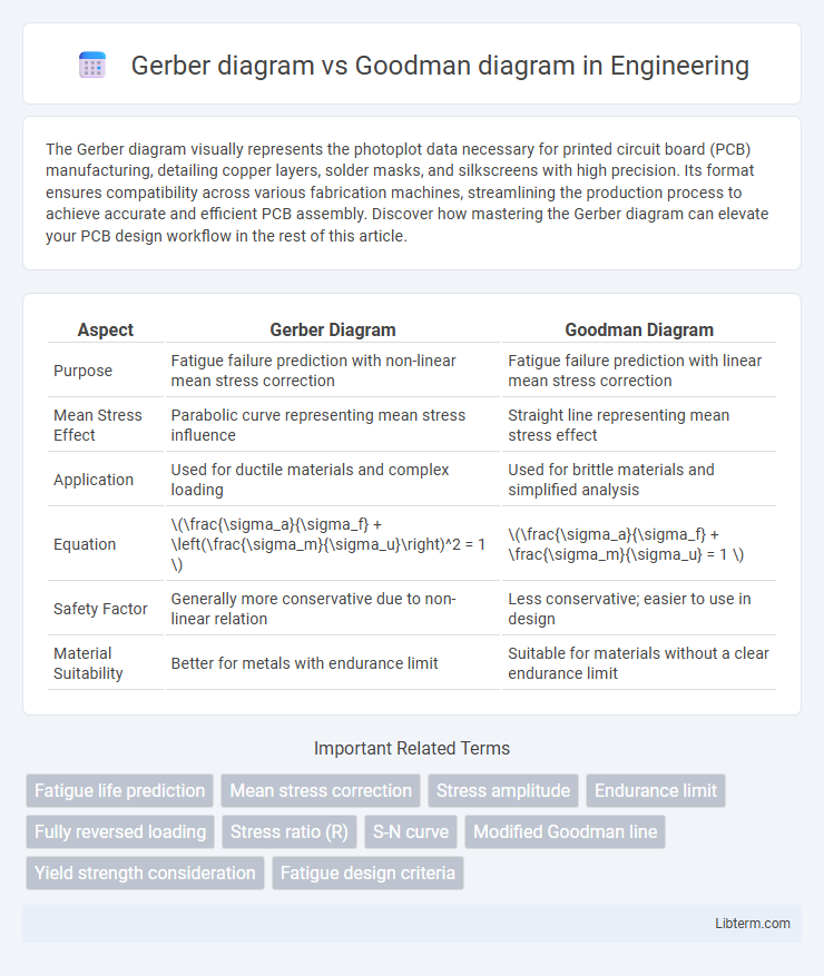
Table of Comparison
| Aspect | Gerber Diagram | Goodman Diagram |
|---|---|---|
| Purpose | Fatigue failure prediction with non-linear mean stress correction | Fatigue failure prediction with linear mean stress correction |
| Mean Stress Effect | Parabolic curve representing mean stress influence | Straight line representing mean stress effect |
| Application | Used for ductile materials and complex loading | Used for brittle materials and simplified analysis |
| Equation | \(\frac{\sigma_a}{\sigma_f} + \left(\frac{\sigma_m}{\sigma_u}\right)^2 = 1 \) | \(\frac{\sigma_a}{\sigma_f} + \frac{\sigma_m}{\sigma_u} = 1 \) |
| Safety Factor | Generally more conservative due to non-linear relation | Less conservative; easier to use in design |
| Material Suitability | Better for metals with endurance limit | Suitable for materials without a clear endurance limit |
Introduction to Fatigue Failure Analysis
Gerber diagram and Goodman diagram are essential tools in fatigue failure analysis, used to predict the durability of materials under cyclic loading. The Gerber diagram represents a parabolic relationship between mean stress and alternating stress, providing accurate failure predictions for ductile materials. In contrast, the Goodman diagram uses a linear approach to estimate fatigue limits, often applied in design safety assessments for brittle materials.
Overview of Gerber and Goodman Diagrams
The Gerber diagram is a graphical representation used to analyze the fatigue life of materials under variable amplitude loading by plotting alternating stress against mean stress with a parabolic curve. The Goodman diagram, on the other hand, uses a linear approach to define the safe stress limits, connecting ultimate tensile strength and endurance limit to predict fatigue failure. Both diagrams serve as critical tools in mechanical engineering for designing components that withstand cyclic stresses, with Gerber providing more accuracy for ductile materials and Goodman being more conservative and simpler to apply.
Fundamental Concepts of Fatigue Loading
The Gerber diagram and Goodman diagram are fundamental tools in fatigue analysis used to predict the endurance limit of materials under varying mean and alternating stresses. The Gerber diagram employs a parabolic curve representing the relationship between mean stress and alternating stress, providing a more accurate estimation for ductile materials by considering material yield strength. In contrast, the Goodman diagram uses a linear approach to estimate fatigue limits, offering a conservative but simpler criterion by linking mean stress directly to ultimate tensile strength.
Gerber Diagram: Principles and Applications
The Gerber diagram is a graphical representation used in fatigue analysis to predict the lifespan of materials under cyclic loading by plotting mean stress against alternating stress. It employs a parabolic curve to model the relationship between mean and alternating stresses, offering increased accuracy for ductile materials compared to the Goodman diagram's linear approach. Widely applied in mechanical engineering and component design, the Gerber diagram effectively helps engineers optimize safety factors and improve durability in rotating shafts, bridges, and aircraft structures.
Goodman Diagram: Principles and Applications
The Goodman diagram is a fundamental tool in fatigue analysis used to predict the failure of materials under cyclic loading by relating mean stress and alternating stress to the material's ultimate tensile strength and endurance limit. It graphically represents the safe and unsafe zones for stress combinations, providing engineers with critical insight for designing components that resist fatigue failure. Widely applied in mechanical and structural engineering, the Goodman diagram helps optimize durability and safety in parts subjected to varying stress ranges.
Key Differences Between Gerber and Goodman Diagrams
Gerber and Goodman diagrams are essential tools in fatigue analysis for predicting failure under cyclic loading, with the key difference lying in their safety factor calculations and curve shapes: the Gerber diagram uses a parabolic curve to represent the relationship between mean stress and alternating stress, providing a more accurate prediction for ductile materials, while the Goodman diagram employs a linear approach, offering a conservative estimate suitable for brittle materials. The Gerber diagram accounts for plastic deformation by considering the non-linear reduction in fatigue strength at higher mean stresses, whereas the Goodman diagram assumes a linear decrease in allowable alternating stress as mean stress increases. This fundamental distinction impacts design decisions and safety margins, with Gerber being preferred for components experiencing fluctuating stresses beyond the elastic limit and Goodman being simpler but more conservative for elastic stress conditions.
Material Selection Criteria Using Fatigue Diagrams
Gerber and Goodman diagrams are essential fatigue failure criteria used in material selection to predict the endurance limits under fluctuating stresses. The Gerber diagram provides a parabolic relationship between mean stress and alternating stress, making it suitable for ductile materials where stress concentration effects are significant. The Goodman diagram offers a linear approximation ideal for brittle materials, emphasizing a conservative approach in fatigue analysis by relating tensile mean stress directly to the material's ultimate tensile strength for safer design choices.
Advantages and Limitations of Gerber vs Goodman Approaches
The Gerber diagram provides a more accurate representation of fatigue life under variable amplitude loading by using a parabolic curve that accounts for mean stress effects, making it advantageous for ductile materials. However, it requires more complex calculations and is less conservative compared to the Goodman diagram, which employs a linear relationship for simplicity and safety but may underestimate fatigue strength under certain conditions. While the Goodman approach is widely used in design for its straightforward application and conservative estimates, Gerber's method enhances precision in fatigue analysis by better reflecting material behavior under fluctuating stresses.
Practical Examples in Engineering Design
The Gerber diagram is widely used in fatigue analysis for ductile materials where stress cycles vary sinusoidally, providing a more accurate estimation of fatigue life under fluctuating stresses, such as in rotating shafts or turbine blades. The Goodman diagram simplifies fatigue design by using a linear approach, making it practical for preliminary design stages in components like bolts and machine frames subjected to variable loads. Engineers often choose the Gerber diagram when dealing with high-cycle fatigue involving complex stress states, while the Goodman diagram is preferred for quick assessments with static or constant mean stresses.
Summary and Recommended Diagram for Specific Use Cases
Gerber diagrams provide a precise approach for fatigue analysis by incorporating nonlinear stress-strain relationships, making them ideal for high-cycle fatigue and components subjected to variable amplitude loading. Goodman diagrams offer a simplified linear method, useful for quick assessments and design conservatism, especially in low to moderate stress ranges and materials with well-defined yield limits. For complex, variable loading scenarios requiring accurate life prediction, Gerber diagrams are recommended, whereas Goodman diagrams suit early design phases and components with primarily static or low-cycle stresses.
Gerber diagram Infographic