Bending moment represents the internal force moment that induces bending in a structural element due to applied loads. Understanding bending moments is crucial for designing safe and efficient beams, bridges, and other load-bearing structures to prevent failure. Explore this article to learn how bending moments affect your constructions and how to calculate them accurately.
Table of Comparison
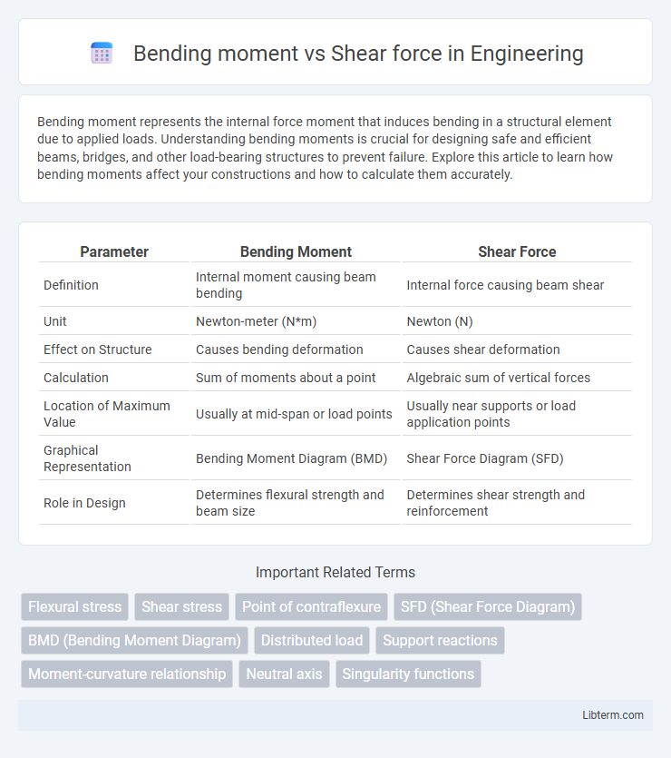
| Parameter | Bending Moment | Shear Force |
|---|---|---|
| Definition | Internal moment causing beam bending | Internal force causing beam shear |
| Unit | Newton-meter (N*m) | Newton (N) |
| Effect on Structure | Causes bending deformation | Causes shear deformation |
| Calculation | Sum of moments about a point | Algebraic sum of vertical forces |
| Location of Maximum Value | Usually at mid-span or load points | Usually near supports or load application points |
| Graphical Representation | Bending Moment Diagram (BMD) | Shear Force Diagram (SFD) |
| Role in Design | Determines flexural strength and beam size | Determines shear strength and reinforcement |
Introduction to Bending Moment and Shear Force
Bending moment and shear force are fundamental concepts in structural engineering that describe internal forces within a beam subjected to external loads. The shear force at a section of a beam measures the internal force parallel to the cross-section, while the bending moment quantifies the rotational effect caused by these forces about that section. Understanding the distribution of shear force and bending moment along a beam is essential for designing safe and efficient structural elements.
Fundamental Concepts in Structural Analysis
Bending moment and shear force are critical parameters in structural analysis that describe internal forces within a beam subjected to external loads. The bending moment at a section represents the rotational effect caused by external loads, influencing beam curvature and stress distribution, while the shear force indicates the internal force parallel to the cross-section, responsible for material shear failure. Understanding their variation along the beam length enables accurate design and ensures structural safety by preventing excessive bending stresses and shear fractures.
Definitions: Bending Moment vs. Shear Force
Bending moment refers to the internal moment that causes a beam or structural element to bend, measured as the force multiplied by the distance from a point of interest. Shear force represents the internal force that acts perpendicular to the axis of the structural element, resisting sliding between sections. Both bending moment and shear force are critical for analyzing stress distribution and designing safe load-bearing structures.
Key Differences Between Bending Moment and Shear Force
Bending moment measures the internal moment that causes a beam to bend, expressed in units like Newton-meters (Nm), while shear force quantifies the internal force acting perpendicular to the cross-section, measured in Newtons (N). Bending moment varies along the length of a beam and influences its curvature and deflection, whereas shear force impacts the beam's tendency to shear or slide along the cross-section. Structural analysis leverages bending moment diagrams to assess flexural stress and shear force diagrams to evaluate shear stress, highlighting their distinct roles in design and safety assessment.
Importance in Structural Design and Engineering
Bending moment and shear force are fundamental parameters in structural design that determine the internal stresses within beams and other structural elements. Accurate analysis of bending moments ensures that materials can withstand rotational forces without failure, while shear force analysis prevents sudden shear failures by addressing transverse loading effects. Engineers prioritize these calculations to optimize structural integrity, safety, and material efficiency in buildings, bridges, and other critical infrastructures.
Mathematical Expressions and Units
Bending moment (M) is mathematically expressed as M = F x d, where F is the applied force in newtons (N) and d is the perpendicular distance in meters (m), resulting in units of newton-meters (N*m). Shear force (V) is defined as the internal force parallel to the cross-section, measured in newtons (N) and calculated by summing vertical forces acting on a beam segment. Understanding these mathematical expressions and units is crucial for analyzing structural behavior under loads for engineering applications.
Diagrammatic Representation: Shear Force and Bending Moment Diagrams
Shear Force and Bending Moment Diagrams visually represent internal forces within a beam subjected to loads, showing shear force and bending moment variation along the beam length. The Shear Force Diagram (SFD) typically exhibits abrupt changes at point loads and linear variation under uniform distributed loads, while the Bending Moment Diagram (BMD) reflects the cumulative effect of shear forces, with maximum moments often occurring where shear force crosses zero. These diagrams are crucial in structural engineering for identifying critical stress points, enabling efficient design and safety assessment of beams and structural members.
Relationship Between Shear Force and Bending Moment
Shear force represents the internal force parallel to a beam's cross-section, while bending moment measures the internal moment causing the beam to bend. The relationship between shear force (V) and bending moment (M) is mathematically defined by the differential equation dM/dx = V, indicating that the rate of change of the bending moment along the beam length equals the shear force at that section. Understanding this relationship is crucial for structural analysis and design, ensuring beams can safely withstand applied loads without failure.
Common Applications in Real-World Structures
Bending moment and shear force are critical in designing bridges, beams, and frames to ensure structural integrity under loads. In real-world applications like skyscraper frameworks and highway overpasses, accurate calculation of bending moments and shear forces prevents material failure and catastrophic collapse. Structural engineers utilize these parameters to optimize reinforcement placement, enhancing safety and durability in construction.
Summary and Practical Considerations
Bending moment and shear force are fundamental concepts in structural engineering used to analyze internal forces within beams subjected to loads. The bending moment measures the tendency of a beam to bend, calculated as the moment of internal forces about a point, while shear force represents the internal force parallel to the cross-section, responsible for sliding failure. Understanding their distribution is critical for designing safe and efficient structures, selecting appropriate beam sizes, and ensuring materials withstand imposed stresses.
Bending moment Infographic