Transition fit refers to a type of interference fit where two parts are assembled with minimal clearance or small interference, providing a balance between ease of assembly and secure positioning. This fit ensures components are held firmly without the risk of excessive stress or deformation, commonly used in mechanical engineering and manufacturing applications. Discover how understanding transition fits can optimize your designs by reading the full article.
Table of Comparison
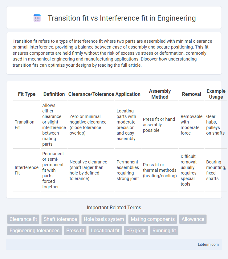
| Fit Type | Definition | Clearance/Tolerance | Application | Assembly Method | Removal | Example Usage |
|---|---|---|---|---|---|---|
| Transition Fit | Allows either clearance or slight interference between mating parts | Zero or minimal negative clearance (close tolerance overlap) | Locating parts with moderate precision and easy assembly | Press fit or hand assembly possible | Removable with moderate force | Gear hubs, pulleys on shafts |
| Interference Fit | Permanent or semi-permanent fit with parts forced together | Negative clearance (shaft larger than hole by defined tolerance) | Permanent assemblies requiring strong joint | Press fit or thermal methods (heating/cooling) | Difficult removal; usually requires special tools | Bearing mounting, fixed shafts |
Introduction to Fits: Transition vs Interference
Transition fit occurs when the assembled parts may have either a small clearance or slight interference, allowing for moderate precision and easy assembly or disassembly. Interference fit involves parts designed to have a negative clearance, ensuring a tight, permanent joint through friction or deformation. Understanding the distinctions between these fits is crucial for selecting the appropriate machining tolerances and assembly methods in engineering applications.
Definition of Transition Fit
Transition fit defines the condition where the shaft and hole dimensions allow either a clearance or a slight interference once assembled, providing a balanced tolerance that ensures precise alignment without excessive force. It is used when a controlled tightness is required, offering flexibility between easy assembly and a secure fit. This fit is commonly specified by engineering standards such as ISO system of limits and fits.
Definition of Interference Fit
Interference fit, also known as a press fit or friction fit, occurs when two parts are designed with dimensions that cause the inner component to be slightly larger than the outer component's hole, resulting in a tight assembly through material deformation. This type of fit generates a strong mechanical connection due to the high contact pressure between the mating surfaces, often requiring force or heating to assemble or disassemble. In contrast, transition fit allows for a range of clearances or slight interference, enabling easier assembly with limited movement or slip between parts.
Key Differences Between Transition and Interference Fits
Transition fit allows slight clearance or light interference between mating parts, enabling easy assembly with limited play, while interference fit ensures permanent joining by creating a tight grip through controlled overlapping dimensions. Transition fits typically have tolerances that balance between clearance and tightness, suitable for applications requiring accurate alignment without excessive force. Interference fits, with negative allowances, are used where rigidity and resistance to movement under load are critical, such as in press-fit bearings or shaft-hub assemblies.
Applications of Transition Fit
Transition fit is commonly applied in mechanical assemblies where moderate precision and ease of assembly are required, such as in coupling shafts and hubs or mounting gears on shafts. It provides a compromise between clearance fit and interference fit, allowing for controlled tightness that can accommodate slight misalignments while maintaining sufficient friction to prevent relative motion. Typical applications include automotive components, machine tool spindles, and pump shafts where components must be securely joined yet remain serviceable.
Applications of Interference Fit
Interference fit is widely used in mechanical engineering applications requiring strong, permanent joints such as securing gears, bearings, and pulleys on shafts to transmit torque without slippage. This fit type provides high load-bearing capacity and resistance to vibration, making it ideal for automotive engines, heavy machinery, and aerospace components where reliability and safety are critical. The metal deformation in interference fit ensures a tight, stress-distributed connection, enhancing durability and minimizing the need for additional fasteners or adhesives.
Advantages of Transition Fit
Transition fit offers the advantage of providing a balance between ease of assembly and maintaining sufficient precision to prevent relative motion between parts. It allows for moderate force during installation, reducing the risk of damaging components compared to interference fits. This fit type is ideal for assemblies requiring precise alignment with the ability to disassemble without excessive wear or deformation.
Advantages of Interference Fit
Interference fit provides superior strength and load-bearing capacity by creating a permanent, tight connection between components, which minimizes relative movement and vibration. This fit ensures precise alignment and enhances the durability and reliability of mechanical assemblies under high-stress conditions. The high frictional force generated in an interference fit improves resistance to loosening, making it ideal for critical applications such as heavy machinery and automotive components.
Factors Influencing Fit Selection
Material properties such as thermal expansion and hardness significantly influence the choice between transition fit and interference fit, ensuring proper assembly and performance. Dimensional tolerances and surface finish determine the achievable precision and affect the ease of assembly or disassembly in mechanical components. Application requirements, including load conditions, vibration levels, and the need for relative motion, guide the selection of fit type to maintain reliability and functionality.
Choosing the Right Fit for Engineering Design
Transition fit provides a balance between clearance and interference, allowing components to either slide together with minimal force or fit tightly, making it suitable for assemblies requiring moderate precision and ease of disassembly. Interference fit, characterized by permanent or near-permanent joint strength due to intentional overlap of dimensions, is ideal for applications demanding high load transmission and resistance to relative movement under stress. Engineers select the appropriate fit based on factors like load requirements, material properties, thermal expansion, and the need for maintenance or replacement in the design lifecycle.
Transition fit Infographic