A series circuit connects components end-to-end so the same current flows through each element, making the total resistance the sum of individual resistances. Voltage drops across each component add up to the total voltage supplied by the source, which directly impacts how your circuit performs in practical applications. Explore the rest of the article to understand how series circuits influence electrical devices and how to calculate their parameters effectively.
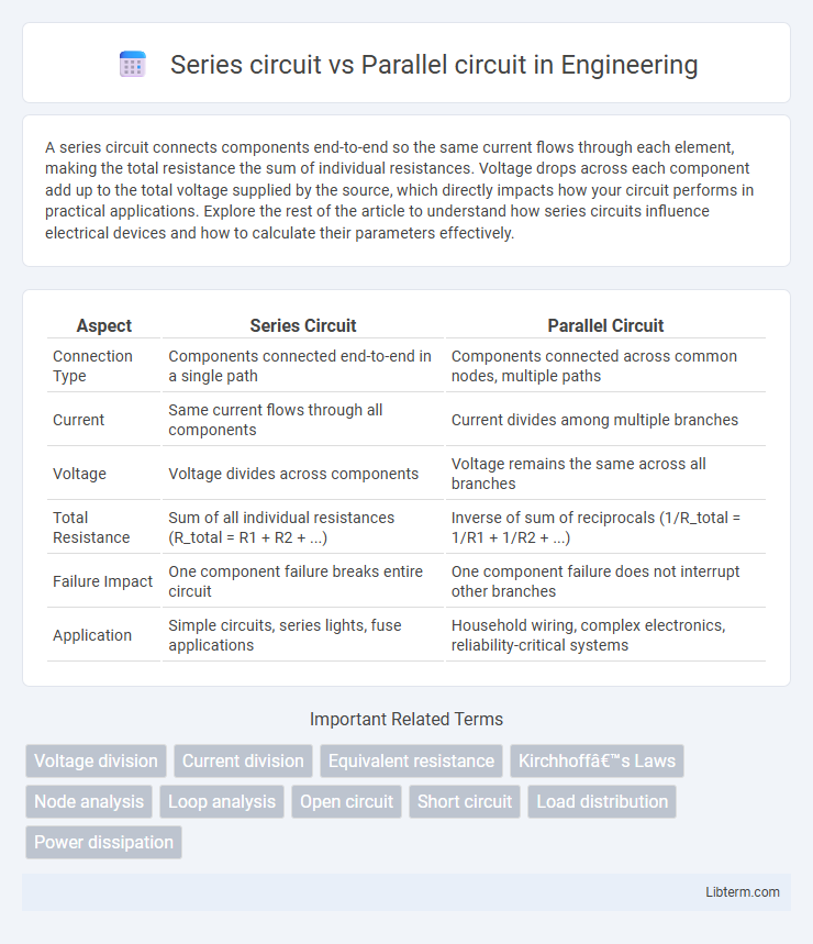
Table of Comparison
| Aspect | Series Circuit | Parallel Circuit |
|---|---|---|
| Connection Type | Components connected end-to-end in a single path | Components connected across common nodes, multiple paths |
| Current | Same current flows through all components | Current divides among multiple branches |
| Voltage | Voltage divides across components | Voltage remains the same across all branches |
| Total Resistance | Sum of all individual resistances (R_total = R1 + R2 + ...) | Inverse of sum of reciprocals (1/R_total = 1/R1 + 1/R2 + ...) |
| Failure Impact | One component failure breaks entire circuit | One component failure does not interrupt other branches |
| Application | Simple circuits, series lights, fuse applications | Household wiring, complex electronics, reliability-critical systems |
Introduction to Series and Parallel Circuits
Series circuits consist of components connected end-to-end, forming a single path for current flow, where the total resistance equals the sum of individual resistances, affecting voltage distribution. Parallel circuits have components connected across the same two points, providing multiple pathways for current, and the overall resistance decreases as more branches are added. Understanding the fundamental differences in current flow, voltage drop, and resistance behavior is crucial for analyzing electrical circuit functionality.
Basic Definitions: Series vs. Parallel Circuit
A series circuit connects components in a single path, so the same current flows through all elements, while voltage divides among them. In contrast, a parallel circuit connects components across multiple paths, allowing each element to receive the full voltage independently. Series circuits have a total resistance equal to the sum of individual resistances, whereas parallel circuits have a total resistance lower than any single branch due to the inverse sum of conductances.
Structure and Components Comparison
A series circuit consists of components connected end-to-end, forming a single path for current flow, while a parallel circuit features branches where each component is connected across the same voltage source. Components in a series circuit share the same current but have different voltage drops, whereas in parallel circuits, each component experiences the same voltage but carries varying currents. The structural difference impacts overall circuit behavior: series circuits depend on the continuity of every component for current flow, whereas parallel circuits allow independent operation of components.
Voltage Distribution in Series and Parallel Circuits
In a series circuit, voltage divides across each component proportionally to their resistance, resulting in the sum of individual voltages equaling the total supply voltage. In contrast, a parallel circuit maintains a constant voltage across all branches, equal to the source voltage, regardless of the differing resistances. Understanding voltage distribution is crucial for designing electrical systems that require predictable voltage levels for each component.
Current Flow Differences
In a series circuit, current flows through each component sequentially, resulting in the same current value across all elements due to a single path for electron movement. In contrast, a parallel circuit divides the total current among multiple branches, with each branch receiving a current inversely proportional to its resistance, maintaining the same voltage across all components. These fundamental differences affect the design and functionality of electrical systems, especially in controlling current distribution and maintaining circuit integrity.
Resistance Behavior in Both Circuits
In a series circuit, the total resistance is the sum of all individual resistances, causing an increase in overall resistance as more resistors are added. In contrast, a parallel circuit decreases the total resistance since the reciprocal of the total resistance equals the sum of the reciprocals of each individual resistance. This fundamental difference affects current distribution, with series circuits experiencing uniform current and parallel circuits experiencing voltage uniformity across components.
Practical Applications in Everyday Devices
Series circuits are commonly used in applications like string lights and old-style Christmas lights, where current flows through each component sequentially, causing the entire circuit to fail if one element breaks. Parallel circuits dominate household wiring, allowing multiple devices like lamps and appliances to operate independently without affecting each other's performance. Practical devices benefit from parallel circuits by ensuring consistent voltage across components, which enhances safety and functionality in everyday electrical systems.
Advantages and Disadvantages
A series circuit offers simplicity and easy control of current flow, with all components sharing the same current, making it ideal for applications requiring a uniform current. However, its main disadvantage is that if one component fails, the entire circuit is interrupted, causing all devices to stop functioning. In contrast, a parallel circuit ensures each component receives the full voltage independently, providing greater reliability since failure in one branch does not affect others, but it requires more complex wiring and can lead to increased current demand on the power source.
Common Troubleshooting and Safety Tips
Series circuits often cause issues such as increased resistance leading to voltage drops, while parallel circuits may experience uneven current distribution causing component failure. Troubleshooting series circuits requires checking continuity and identifying single points of failure, whereas parallel circuits demand inspection of individual branches and connections. For safety, always ensure the power is off before testing, use insulated tools, and verify components are rated for the circuit's voltage and current.
Conclusion: Choosing the Right Circuit Type
Selecting the appropriate circuit type depends on the specific application requirements: series circuits offer simplified current flow with components sharing the same current, making them ideal for devices where sequential operation is crucial. Parallel circuits provide independent voltage paths, ensuring that failure of one component does not interrupt the entire system, suitable for complex electrical networks and household wiring. Understanding the distinct characteristics of series and parallel circuits allows engineers to optimize performance, reliability, and safety in electrical designs.
Series circuit Infographic