Flatness tolerance defines the allowable deviation of a surface from a perfectly flat plane, ensuring precision in manufacturing and assembly processes. Controlling flatness is critical for parts that must fit together seamlessly or function reliably under pressure. Explore the article to understand how implementing optimal flatness tolerance benefits your projects and improves overall product quality.
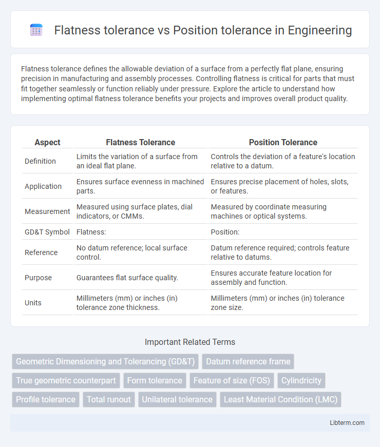
Table of Comparison
| Aspect | Flatness Tolerance | Position Tolerance |
|---|---|---|
| Definition | Limits the variation of a surface from an ideal flat plane. | Controls the deviation of a feature's location relative to a datum. |
| Application | Ensures surface evenness in machined parts. | Ensures precise placement of holes, slots, or features. |
| Measurement | Measured using surface plates, dial indicators, or CMMs. | Measured by coordinate measuring machines or optical systems. |
| GD&T Symbol | Flatness: | Position: |
| Reference | No datum reference; local surface control. | Datum reference required; controls feature relative to datums. |
| Purpose | Guarantees flat surface quality. | Ensures accurate feature location for assembly and function. |
| Units | Millimeters (mm) or inches (in) tolerance zone thickness. | Millimeters (mm) or inches (in) tolerance zone size. |
Introduction to Geometric Dimensioning and Tolerancing (GD&T)
Flatness tolerance controls the uniformity of a surface by restricting the deviation from an ideal plane, ensuring that every point lies within two parallel planes separated by the specified tolerance value. Position tolerance defines the permissible variation in the location of a feature relative to its true position, critical for maintaining the accurate assembly and function of components. In Geometric Dimensioning and Tolerancing (GD&T), flatness is a form control characteristic focusing on surface quality, while position tolerance is a location control characteristic that governs the spatial accuracy of features for functional fit.
Defining Flatness Tolerance
Flatness tolerance defines the allowable deviation within a perfectly flat surface, ensuring the surface lies between two parallel planes separated by the specified tolerance value. Unlike position tolerance, which controls the location of a feature in space relative to a datum, flatness tolerance strictly addresses surface form without reference to any datum. This geometric tolerance is crucial for maintaining functional contact and uniformity across mating surfaces in precision engineering.
Understanding Position Tolerance
Position tolerance specifies the permissible variation in the exact location of a feature relative to a datum, ensuring functional relationships between parts in assembly. Flatness tolerance, in contrast, controls surface variation to maintain a uniform plane without reference to other features. Understanding position tolerance is crucial for accurately controlling the spatial relationship of holes, slots, or other features to achieve proper fit and function in mechanical design.
Key Differences Between Flatness and Position Tolerance
Flatness tolerance controls the variation of a surface from an ideal flat plane, ensuring the entire surface lies within two parallel planes separated by the tolerance value, without reference to any datums. Position tolerance defines the allowable deviation of a feature's location, orientation, or axis relative to specified datums, ensuring precise placement within a specified cylindrical or positional zone. Unlike flatness, which is a form tolerance affecting surface quality, position tolerance directly impacts the functional relationship and assembly fit between parts.
Importance of Flatness Tolerance in Manufacturing
Flatness tolerance ensures the uniformity of a surface by limiting deviations from an ideal plane, which is critical for proper assembly and function of mechanical parts. Unlike position tolerance that controls the location of features relative to a datum, flatness tolerance directly affects the quality of mating surfaces, reducing wear and improving sealing capabilities. Maintaining strict flatness tolerance minimizes machining errors, enhances product reliability, and supports tight fit requirements in precision manufacturing.
Role of Position Tolerance in Assembly Accuracy
Position tolerance plays a critical role in assembly accuracy by ensuring each feature's location adheres to exact geometric constraints, minimizing misalignment during component fit. Unlike flatness tolerance, which controls the surface profile of individual parts, position tolerance directly governs the spatial placement essential for functional assemblies. Precise position tolerance reduces cumulative errors, enhancing the consistency and reliability of assembled products in manufacturing processes.
Interpretation of Flatness Symbols in Engineering Drawings
Flatness tolerance controls the variation of a surface from an ideal plane, ensuring all points lie within two parallel planes, which is crucial for maintaining consistent surface quality in engineering drawings. Position tolerance defines the acceptable deviation of a feature's location relative to a true coordinate or datum, emphasizing precise placement of holes, pins, or other geometric elements. Interpreting flatness symbols involves recognizing a parallelogram or a flatness flag within the geometric dimensioning and tolerancing (GD&T) framework, which specifies the allowable flatness variation without reference to datum, differentiating it from positional tolerance that always relates to datum references.
Interpreting Position Tolerance Symbols and Feature Control Frames
Position tolerance symbols define the allowable deviation of a feature's location through a Feature Control Frame, specifying exact geometric constraints like true position with reference datums. Flatness tolerance, conversely, controls the surface uniformity without datum references, ensuring the entire surface lies within a specified tolerance zone parallel to a theoretical plane. Understanding Position Tolerance involves interpreting symbols within the Feature Control Frame that convey the type of geometric control, tolerance value, and datum references critical for precise assembly and function.
Practical Examples: Flatness vs Position Applications
Flatness tolerance controls the surface evenness of a single feature, ensuring that the entire surface lies within two parallel planes, which is critical in applications such as sealing surfaces or machined flats on engine blocks to prevent leaks. Position tolerance governs the exact location of a feature relative to datums, essential in assembly processes like locating bolt holes on a mounting flange to guarantee proper alignment and fit. For example, in automotive manufacturing, flatness tolerance ensures a smooth gasket surface for engine heads, while position tolerance ensures that bolt holes precisely align for component assembly.
Choosing the Right Tolerance for Your Design Needs
Choosing between flatness tolerance and position tolerance depends on the specific requirements of your design, emphasizing surface uniformity or precise element location. Flatness tolerance controls the deviation of a surface from a perfectly planar condition, critical for sealing surfaces and mating components. Position tolerance ensures the exact placement of features relative to datum points, essential for assembly alignment and functional fit.
Flatness tolerance Infographic