First angle projection is a standardized method in technical drawing where the object is positioned between the observer and the plane of projection, commonly used in Europe and Asia. This technique provides clear and accurate views of an object's dimensions, essential for engineering and architectural designs. Explore this article to understand how first angle projection enhances your drafting precision and communication.
Table of Comparison
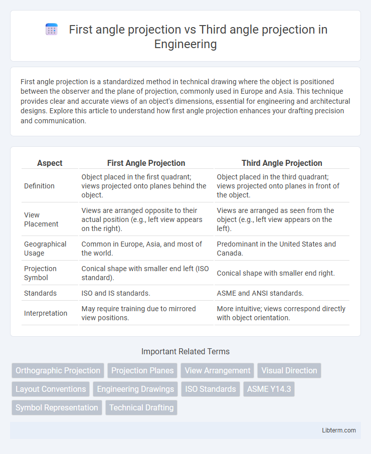
| Aspect | First Angle Projection | Third Angle Projection |
|---|---|---|
| Definition | Object placed in the first quadrant; views projected onto planes behind the object. | Object placed in the third quadrant; views projected onto planes in front of the object. |
| View Placement | Views are arranged opposite to their actual position (e.g., left view appears on the right). | Views are arranged as seen from the object (e.g., left view appears on the left). |
| Geographical Usage | Common in Europe, Asia, and most of the world. | Predominant in the United States and Canada. |
| Projection Symbol | Conical shape with smaller end left (ISO standard). | Conical shape with smaller end right. |
| Standards | ISO and IS standards. | ASME and ANSI standards. |
| Interpretation | May require training due to mirrored view positions. | More intuitive; views correspond directly with object orientation. |
Introduction to Projection Methods
First angle projection positions the object between the observer and the plane of projection, commonly used in European countries and following ISO standards, resulting in views arranged opposite to their actual locations. Third angle projection places the plane of projection between the observer and the object, widely adopted in the United States and Canada, with views arranged as if unfolded around the object for intuitive visualization. Both methods are fundamental in technical drawing, facilitating accurate communication of three-dimensional objects on two-dimensional media.
Understanding First Angle Projection
First Angle Projection is a method of orthographic projection predominantly used in Europe and Asia, where the object is placed between the observer and the plane of projection. This technique results in views that are arranged such that the top view is below the front view, and the right side view is on the left side of the front view, requiring a spatial understanding of object orientation. Understanding First Angle Projection is essential for interpreting engineering drawings accurately in international manufacturing contexts where this standard is prevalent.
Basics of Third Angle Projection
Third angle projection is a standard method used predominantly in the United States and Canada for technical drawings. It positions the object between the observer and the plane of projection, resulting in the top view placed above the front view and the right view placed to the right of the front view. This method simplifies interpretation by representing objects as viewed directly from each side, enhancing clarity in engineering and architectural blueprints.
Key Differences between First and Third Angle Projection
First angle projection places the object between the observer and the plane of projection, resulting in views arranged opposite to their real-world positions, while third angle projection positions the plane of projection between the observer and the object, producing views aligned with their actual locations. Standard practice in Europe and Asia favors first angle projection, whereas third angle projection is commonly used in the United States and Canada. The key difference lies in the orientation and arrangement of the views on the drawing sheet, impacting how technical drawings communicate spatial information.
Symbol Representation and Standardization
First angle projection uses a symbol featuring a truncated cone with a smaller circle on the left side and a larger circle on the right, aligning with ISO and European standards. Third angle projection displays the symbol with the larger circle on the left and the smaller circle on the right, following ASME and ANSI standards predominantly in the United States. These distinct symbols ensure clear communication in engineering drawings by visually distinguishing the projection method applied.
Applications in Engineering Drawing
First angle projection is predominantly used in Europe and Asia for mechanical and architectural engineering drawings, providing standardized views that align with ISO conventions. Third angle projection, favored in the United States and Canada, facilitates easier interpretation on manufacturing floors by positioning the object between the observer and the plane of projection, adhering to ASME standards. Both methods ensure accurate visualization of components, but selection depends on regional industry practices and compliance with international or national drafting standards.
Regional Preferences and Industry Standards
First angle projection is predominantly used in Europe and Asia, adhering to ISO standards, while third angle projection is the standard in the United States and Canada, following ASME guidelines. Automotive and aerospace industries in Europe prefer first angle projection for technical drawings, whereas manufacturing and construction sectors in North America rely on third angle projection for clarity and uniformity. Understanding these regional preferences and industry standards is crucial for global collaboration and accurate interpretation of engineering drawings.
Advantages of First Angle Projection
First angle projection offers advantages such as a clearer association between views and the actual object, making it intuitive for visualizing the placement of features in technical drawings. It provides a standardized approach widely used in Europe and Asia, enhancing communication and reducing errors in manufacturing and engineering processes. The consistent layout of views in first angle projection facilitates easier dimensioning and interpretation for designers and engineers familiar with this method.
Benefits of Third Angle Projection
Third angle projection offers intuitive visualization by placing the object between the observer and the projection plane, simplifying interpretation for engineers and fabricators. It aligns with the ISO and ASME standards widely used in the United States and Canada, promoting clear communication in manufacturing and design industries. The method reduces the risk of drawing misinterpretation, enhancing accuracy and efficiency in technical drawings.
Choosing the Right Projection Method
Selecting the right projection method depends on industry standards and regional preferences, with first angle projection commonly used in Europe and third angle projection favored in North America. Understanding the differences, such as first angle positioning the object between the observer and the plane, while third angle places the plane between the observer and the object, ensures accurate interpretation. Clear communication in technical drawings requires adhering to the correct projection method to avoid manufacturing errors and improve collaboration.
First angle projection Infographic