The Smith diagram is an essential graphical tool used in electrical engineering to represent complex impedance and reflection coefficients in RF circuits. It simplifies the analysis and design of transmission lines and matching networks by mapping normalized impedances onto a circular chart. Explore the article to understand how the Smith diagram can enhance your microwave circuit design.
Table of Comparison
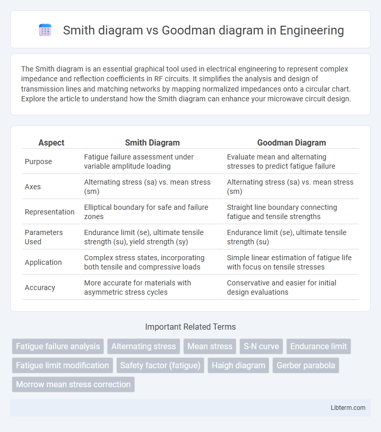
| Aspect | Smith Diagram | Goodman Diagram |
|---|---|---|
| Purpose | Fatigue failure assessment under variable amplitude loading | Evaluate mean and alternating stresses to predict fatigue failure |
| Axes | Alternating stress (sa) vs. mean stress (sm) | Alternating stress (sa) vs. mean stress (sm) |
| Representation | Elliptical boundary for safe and failure zones | Straight line boundary connecting fatigue and tensile strengths |
| Parameters Used | Endurance limit (se), ultimate tensile strength (su), yield strength (sy) | Endurance limit (se), ultimate tensile strength (su) |
| Application | Complex stress states, incorporating both tensile and compressive loads | Simple linear estimation of fatigue life with focus on tensile stresses |
| Accuracy | More accurate for materials with asymmetric stress cycles | Conservative and easier for initial design evaluations |
Introduction to Fatigue Analysis
Smith diagram and Goodman diagram are essential tools in fatigue analysis for evaluating the safety of materials under cyclic loading. The Goodman diagram plots mean stress versus alternating stress to determine fatigue limits, while the Smith diagram incorporates these stresses into a graphical representation for more precise life prediction. Both diagrams help engineers assess material endurance and prevent failure by accounting for varying stress amplitudes and mean stresses in mechanical components.
Overview of Smith Diagram
Smith Diagram represents a graphical method for analyzing fluctuating stresses in materials, particularly emphasizing the relationship between alternating stress and mean stress. It helps in visualizing stress limits to predict fatigue life and design safer mechanical components. Unlike the Goodman Diagram, which uses linear approximations, the Smith Diagram offers more nuanced elliptical curves reflecting material endurance more accurately under cyclic loading.
Overview of Goodman Diagram
The Goodman diagram is a widely used graphical method in fatigue analysis to evaluate the relationship between mean stress and alternating stress, helping to predict failure under cyclic loading conditions. It plots the allowable alternating stress against mean stress, forming a straight line from the material's fatigue limit at zero mean stress to its ultimate tensile strength at zero alternating stress, providing engineers a conservative failure criterion. Unlike the Smith diagram, which uses an elliptical curve, the Goodman diagram offers a simpler, linear approximation ideal for preliminary design assessments and failure evaluation in metals.
Construction of Smith Diagram
The construction of the Smith diagram involves plotting complex reflection coefficients on a normalized impedance plane using a set of constant resistance and reactance circles. It graphically represents transmission line characteristics for impedance matching and reflection analysis, facilitating easy visualization of impedance transformations. In contrast, the Goodman diagram is primarily used for fatigue analysis in materials, displaying mean stress versus alternating stress, which is unrelated to the impedance plotting approach of the Smith diagram.
Construction of Goodman Diagram
The construction of the Goodman diagram involves plotting the mean stress (sm) on the horizontal axis and the alternating stress (sa) on the vertical axis to evaluate fatigue failure criteria. The diagram connects the endurance limit (Se) at zero mean stress and the ultimate tensile strength (Su) at zero alternating stress with a straight line, forming the failure boundary. This graphical method enables precise determination of safe stress combinations under fluctuating loads, contrasting with the Smith diagram which often uses a curved boundary for fatigue analysis.
Key Differences Between Smith and Goodman Diagrams
Smith diagrams emphasize alternating and mean stress relationships for fatigue failure prediction, primarily using elliptical failure criteria. Goodman diagrams focus on the linear relation between mean stress and alternating stress, providing a conservative approach for material fatigue limits. Unlike Goodman diagrams, Smith diagrams incorporate safety factors more closely related to material endurance limits, enhancing design accuracy under varying cyclic loads.
Applications in Engineering Design
Smith diagram and Goodman diagram are essential tools in engineering design for fatigue analysis and life prediction of materials under cyclic loading. The Goodman diagram is widely used for evaluating the safety of components subjected to fluctuating stresses by plotting mean stress versus alternating stress, allowing engineers to assess fatigue limits more conservatively. Smith diagram offers a refined approach by incorporating mean stress effects with material-specific parameters, making it particularly valuable in optimizing mechanical components like shafts and springs for enhanced fatigue resistance in aerospace and automotive industries.
Advantages and Limitations of Smith Diagram
Smith diagram offers a clear graphical representation of fatigue strength under variable loading by correlating mean stress and alternating stress, simplifying complex fatigue data interpretation. Its primary advantage lies in visualizing safe and failure regions for materials under cyclic stress, aiding engineers in design decisions under fluctuating loads. However, the Smith diagram is limited by its assumption of linear damage accumulation and may not accurately predict fatigue life for materials exhibiting non-linear or multi-axial stress behaviors.
Advantages and Limitations of Goodman Diagram
The Goodman diagram is widely favored for its simplicity in representing the relationship between mean stress and alternating stress, providing clear design limits for fatigue analysis in mechanical components. Its primary advantage lies in establishing conservative safety boundaries for materials under fluctuating loads, facilitating straightforward interpretation and application in engineering designs. However, the Goodman diagram's limitation is its assumption of a linear failure criterion, which may not accurately capture the complex behavior of materials under varying stress states, potentially leading to overly conservative or non-conservative predictions compared to more detailed methods like the Smith diagram.
Choosing the Right Diagram for Fatigue Assessment
Smith and Goodman diagrams are essential tools in fatigue assessment, with Smith diagrams primarily used for mean stress correction in rotating bending fatigue scenarios, while Goodman diagrams are preferred for axial loading and tensile-compressive stress states. Selecting the appropriate diagram depends on the loading conditions and material behavior; Goodman diagrams offer conservative failure predictions for ductile materials under fluctuating stresses, whereas Smith diagrams provide more detailed interaction between mean and alternating stresses. Engineers prioritize Goodman diagrams in design for safety-critical applications, whereas Smith diagrams are favored in fatigue life estimation of components subjected to combined stress states.
Smith diagram Infographic