Function Block Diagrams (FBD) visually represent the logical relationships and data flow between functions or components in a system, allowing for easier understanding and troubleshooting of complex processes. This graphical programming language is widely used in automation and control engineering to design, analyze, and simulate systems through interconnected function blocks. Explore the rest of the article to deepen your knowledge of how FBDs can optimize your system design and implementation.
Table of Comparison
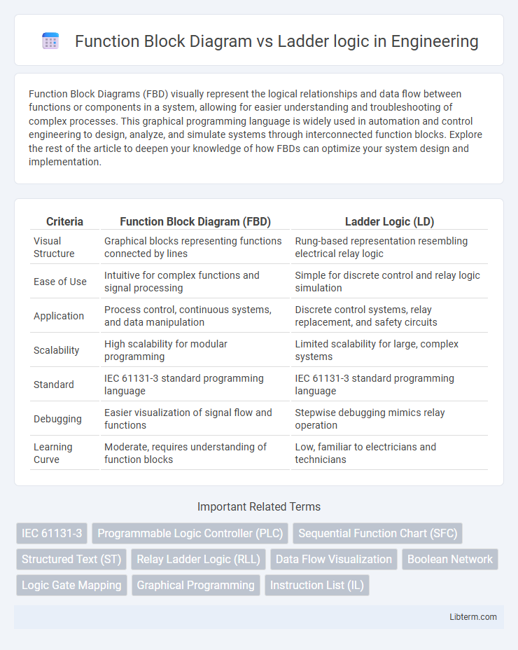
| Criteria | Function Block Diagram (FBD) | Ladder Logic (LD) |
|---|---|---|
| Visual Structure | Graphical blocks representing functions connected by lines | Rung-based representation resembling electrical relay logic |
| Ease of Use | Intuitive for complex functions and signal processing | Simple for discrete control and relay logic simulation |
| Application | Process control, continuous systems, and data manipulation | Discrete control systems, relay replacement, and safety circuits |
| Scalability | High scalability for modular programming | Limited scalability for large, complex systems |
| Standard | IEC 61131-3 standard programming language | IEC 61131-3 standard programming language |
| Debugging | Easier visualization of signal flow and functions | Stepwise debugging mimics relay operation |
| Learning Curve | Moderate, requires understanding of function blocks | Low, familiar to electricians and technicians |
Introduction to Function Block Diagram and Ladder Logic
Function Block Diagram (FBD) and Ladder Logic are two widely used programming languages in industrial automation for programmable logic controllers (PLCs). FBD represents control functions as interconnected blocks illustrating data flow and functionality, ideal for visualizing complex algorithms and control sequences. Ladder Logic mimics electrical relay logic with a graphical design resembling circuit diagrams, favored for its simplicity and ease of troubleshooting in relay-based control systems.
Overview of Industrial Automation Programming Languages
Function Block Diagram (FBD) and Ladder Logic are key industrial automation programming languages used in programmable logic controllers (PLCs). FBD employs graphical blocks representing functions interconnected by data flow lines, making it ideal for complex process control and modular programming. Ladder Logic mimics relay-based circuitry with rungs and contacts, offering intuitive design for discrete control applications and widespread acceptance in legacy systems.
Key Concepts of Ladder Logic
Ladder Logic operates on the principle of relay logic, representing electrical control circuits with graphical symbols such as contacts and coils arranged in rungs, making it intuitive for electricians and engineers. Key concepts include input conditions evaluated as true or false, output coils activated based on logical combinations, and the use of timers, counters, and internal bits to control process sequences. Compared to Function Block Diagram, Ladder Logic emphasizes discrete control flow and straightforward visualization of relay-based logic, enhancing troubleshooting and real-time control in Programmable Logic Controllers (PLCs).
Key Concepts of Function Block Diagram
Function Block Diagram (FBD) utilizes graphical blocks that represent specific functions or operations, making complex processes more understandable and easier to program compared to Ladder Logic. Each function block in FBD connects inputs and outputs through lines, enabling modular and reusable programming structures ideal for continuous process control. Unlike Ladder Logic's relay-based symbols, FBD emphasizes data flow and functional abstraction, allowing for intuitive visualization of control algorithms and seamless integration with advanced automation systems.
Visual Representation Differences
Function Block Diagram (FBD) uses graphical blocks to represent functions and their interconnections, providing a clear and modular visual structure ideal for complex processes. Ladder Logic displays control circuits resembling electrical relay logic, using horizontal rungs and vertical rails that visually emphasize sequential control flow and logical operations. The key difference is FBD's focus on functional modularity with block abstraction, while Ladder Logic prioritizes traditional relay-based schematics for straightforward control and troubleshooting.
Programming Workflow: FBD vs Ladder Logic
Function Block Diagram (FBD) programming workflow emphasizes visual organization by connecting predefined function blocks, enabling intuitive design and modular reuse of control functions. Ladder Logic programming follows a linear, rung-based approach that closely resembles electrical relay logic, facilitating straightforward troubleshooting and sequential logic representation. FBD suits complex control systems requiring clear data flow visualization, while Ladder Logic excels in simpler, sequential process control with easy real-time monitoring.
Advantages and Disadvantages of Ladder Logic
Ladder Logic offers a straightforward and visual programming method resembling electrical relay logic, making it highly intuitive for electricians and engineers familiar with control circuits. Its main advantage lies in ease of troubleshooting and wide industry acceptance, especially in manufacturing environments. However, Ladder Logic can become cumbersome for complex processes due to limited scalability and less efficient handling of advanced data manipulation compared to Function Block Diagram.
Advantages and Disadvantages of Function Block Diagram
Function Block Diagram (FBD) offers a graphical programming approach that simplifies complex control system designs by using reusable function blocks, enhancing modularity and readability compared to Ladder Logic. FBD excels in handling analog signals and process control applications, providing better clarity for continuous control processes, but it may be less intuitive for traditional relay-based logic experienced by electricians familiar with Ladder Logic. The main disadvantages of FBD include a steeper learning curve for beginners and potentially less support in legacy PLC systems compared to the widespread adoption of Ladder Logic.
Application Scenarios: When to Use Each Method
Function Block Diagram (FBD) excels in complex process control and multi-variable systems where visual representation of function blocks simplifies understanding and troubleshooting. Ladder Logic is ideal for discrete control in manufacturing automation, especially where relay logic replacement and ease of programming by electricians are priorities. Engineers typically choose FBD for advanced applications like batch processing, while Ladder Logic remains preferred in sequential control and safety interlocks.
Transitioning Between Ladder Logic and Function Block Diagram
Transitioning between Ladder Logic and Function Block Diagram programming involves understanding their structural differences and application contexts in industrial automation. Function Block Diagram offers a graphical approach emphasizing modularity and reusability through blocks, while Ladder Logic relies on a relay logic-like representation better suited for relay control systems. Efficient transition requires mastering the syntax and operational logic of both, ensuring seamless integration of control strategies and optimization of programmable logic controllers (PLCs).
Function Block Diagram Infographic