Relay logic uses electromechanical switches called relays to control circuits by opening and closing contacts in response to electrical signals. This method is widely applied in industrial automation for its simplicity and reliability in controlling machinery and processes. Explore the rest of the article to understand how relay logic can enhance your control systems.
Table of Comparison
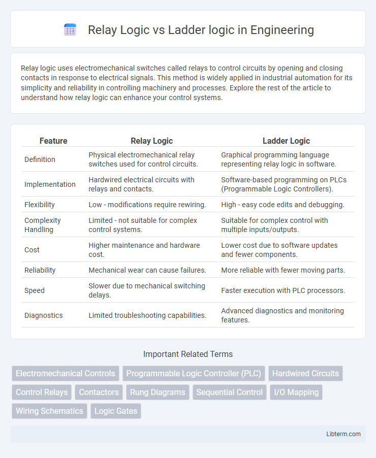
| Feature | Relay Logic | Ladder Logic |
|---|---|---|
| Definition | Physical electromechanical relay switches used for control circuits. | Graphical programming language representing relay logic in software. |
| Implementation | Hardwired electrical circuits with relays and contacts. | Software-based programming on PLCs (Programmable Logic Controllers). |
| Flexibility | Low - modifications require rewiring. | High - easy code edits and debugging. |
| Complexity Handling | Limited - not suitable for complex control systems. | Suitable for complex control with multiple inputs/outputs. |
| Cost | Higher maintenance and hardware cost. | Lower cost due to software updates and fewer components. |
| Reliability | Mechanical wear can cause failures. | More reliable with fewer moving parts. |
| Speed | Slower due to mechanical switching delays. | Faster execution with PLC processors. |
| Diagnostics | Limited troubleshooting capabilities. | Advanced diagnostics and monitoring features. |
Introduction to Relay Logic and Ladder Logic
Relay Logic operates by using electromechanical switches to control machinery and processes through physical relay contacts, enabling straightforward automation in industrial settings. Ladder Logic, a graphical programming language resembling electrical relay diagrams, simulates Relay Logic in programmable logic controllers (PLCs) to provide flexible, software-based control systems. Both methodologies are foundational in industrial automation, with Relay Logic suited for simple applications and Ladder Logic enabling complex, programmable control sequences.
Historical Background and Evolution
Relay logic originated in the early 20th century as an electromechanical control system using relay switches to automate machinery. Ladder logic evolved in the 1960s as a graphical programming language inspired by relay logic diagrams, designed for programmable logic controllers (PLCs) to simplify industrial automation programming. The shift from physical relays to digital PLCs marked a significant evolution, improving reliability, flexibility, and ease of modification in automated control systems.
Core Principles of Relay Logic
Relay logic operates on electromechanical relays to control circuits through physical switches and contacts, emphasizing sequential control and hardwired connections. Its core principles include using normally open (NO) and normally closed (NC) contacts to represent logical operations, enabling straightforward implementation of basic Boolean functions. Unlike ladder logic, relay logic relies solely on physical relay coils and contacts without graphical programming interfaces, making it foundational for understanding automated control systems.
Fundamentals of Ladder Logic
Ladder logic is a graphical programming language designed to replicate the control circuits of relay logic, using symbols to represent electrical relays, contacts, and coils. Its fundamental structure mimics electrical schematics, with rungs representing control logic flows that are easily interpreted by electricians and programmers alike. Ladder logic simplifies troubleshooting and programming of programmable logic controllers (PLCs) by visually illustrating the relationships and conditions required for process automation.
Key Differences between Relay Logic and Ladder Logic
Relay logic uses physical electromechanical relays to control circuits, while ladder logic is a graphical programming language designed to mimic relay logic diagrams for programmable logic controllers (PLCs). Relay logic circuits are hardware-based with limited flexibility and slower response times, whereas ladder logic software provides greater adaptability, faster troubleshooting, and easier modifications. The key difference lies in relay logic's dependency on physical components versus ladder logic's digital nature, enabling advanced automation and integration with modern control systems.
Advantages and Disadvantages of Each Approach
Relay logic offers simplicity and robustness in controlling industrial machinery, making it highly reliable for straightforward automation tasks with minimal programming expertise required; however, its physical relay components result in larger space requirements and slower response times. Ladder logic, favored for its graphical representation and ease of programming within programmable logic controllers (PLCs), enhances flexibility, scalability, and diagnostic capabilities, though it relies on complex software environments and can suffer from increased troubleshooting difficulty in highly complex systems. Choosing between relay and ladder logic depends on the application's complexity, required speed, maintenance capabilities, and scalability needs in industrial automation environments.
Application Areas in Modern Automation
Relay logic is primarily utilized in simple control circuits and legacy systems where electromechanical relay operations are crucial, such as motor starters and basic industrial machinery. Ladder logic dominates programmable logic controllers (PLCs) in modern automation for its graphical representation, ease of troubleshooting, and compatibility with complex sequential processes in manufacturing, assembly lines, and process control. Applications in automotive manufacturing, material handling systems, and building automation favor ladder logic due to its scalability and integration with digital control systems.
Transition from Relay to Ladder Logic in Industry
The transition from relay logic to ladder logic in industry revolutionized control system design by replacing complex wiring with programmable interfaces, significantly improving flexibility and troubleshooting. Ladder logic, a graphical programming language resembling relay circuits, enabled easier updates and integrations with emerging PLC technologies, reducing downtime and maintenance costs. This shift enhanced industrial automation efficiency, paving the way for more sophisticated process control and scalability.
Common Challenges and Troubleshooting
Relay logic and ladder logic both face challenges such as complex wiring diagrams and difficulty in visualizing the control process, which can lead to troubleshooting errors. Fault isolation often requires thorough inspection of physical relays and contacts in relay logic, whereas ladder logic demands careful examination of ladder rungs and instruction sequences in programmable logic controllers (PLCs). Understanding component interactions and using systematic testing methods are essential for efficient resolution of faults in both systems.
Future Trends in Industrial Control Logic
Future trends in industrial control logic emphasize the integration of relay logic and ladder logic with advanced digital automation technologies such as IoT-enabled sensors, AI-driven predictive maintenance, and cloud-based control systems. Ladder logic remains a foundational programming method in PLCs, evolving to support more complex algorithms and real-time data analytics for enhanced process optimization. The convergence of traditional relay logic concepts with modern software tools is driving increased system flexibility, scalability, and cybersecurity resilience in smart manufacturing environments.
Relay Logic Infographic