A ring circuit is a type of electrical wiring system commonly used in residential properties to efficiently distribute power to multiple outlets. This configuration enhances safety by providing two pathways for electrical current, reducing the likelihood of overloads. Discover how a ring circuit works and the benefits it can bring to your home in the rest of this article.
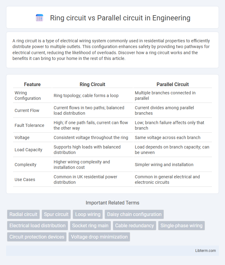
Table of Comparison
| Feature | Ring Circuit | Parallel Circuit |
|---|---|---|
| Wiring Configuration | Ring topology; cable forms a loop | Multiple branches connected in parallel |
| Current Flow | Current flows in two paths; balanced load distribution | Current divides among parallel branches |
| Fault Tolerance | High; if one path fails, current can flow the other way | Low; branch failure affects only that branch |
| Voltage | Consistent voltage throughout the ring | Same voltage across each branch |
| Load Capacity | Supports high loads with balanced distribution | Load depends on branch capacity; can be uneven |
| Complexity | Higher wiring complexity and installation cost | Simpler wiring and installation |
| Use Cases | Common in UK residential power distribution | Common in general electrical and electronic circuits |
Introduction to Ring and Parallel Circuits
Ring circuits distribute electrical current through a continuous loop of wiring, allowing multiple outlets to be powered from two directions and enhancing load capacity and fault tolerance. Parallel circuits connect each load directly to the power source independently, ensuring consistent voltage across all devices and preventing one appliance from affecting others. Both circuit types are fundamental in residential and commercial wiring, with ring circuits prevalent in UK installations and parallel circuits commonly used worldwide for their simplicity and reliability.
Basic Concepts: What is a Ring Circuit?
A ring circuit is a type of electrical wiring configuration commonly used in residential and commercial buildings where the wiring forms a continuous loop, connecting multiple outlets and devices back to the distribution board. This setup allows electricity to flow along two paths, enhancing reliability and load distribution compared to parallel circuits, where each outlet is connected individually in a singular path. In ring circuits, the redundancy reduces voltage drop and increases safety by providing an alternative path for current if one part of the loop is damaged or interrupted.
Understanding Parallel Circuits
Parallel circuits consist of multiple branches where electrical components are connected across the same voltage source, allowing current to split and flow through each path independently. This configuration ensures that if one branch fails, the remaining paths continue to operate without interruption, which contrasts with ring circuits where current flows in a loop. Understanding parallel circuits is crucial for designing reliable electrical systems that maintain consistent voltage and prevent total circuit failure.
Key Differences Between Ring and Parallel Circuits
Ring circuits loop the wiring back to the distribution board, allowing current to flow in two directions, which provides greater reliability and balanced load distribution. Parallel circuits have multiple branches connected independently to the power source, ensuring each device operates separately but may cause voltage drop under heavy load. Ring circuits can support higher total current and reduce wiring costs, while parallel circuits offer simpler installation and easier fault detection.
Electrical Efficiency Comparison
Ring circuits provide higher electrical efficiency compared to parallel circuits by reducing voltage drop and minimizing current load on individual cables. The continuous loop in ring circuits allows electrical current to flow from two directions, decreasing resistance and energy loss, which enhances overall power distribution efficiency. In contrast, parallel circuits have separate paths with higher resistance and greater voltage drop, leading to increased energy consumption and reduced efficiency in power delivery.
Safety Considerations in Both Circuits
Ring circuits provide enhanced safety through continuous current paths, reducing voltage drops and minimizing overheating risks by evenly distributing electrical loads. Parallel circuits, while simpler in design, can pose higher risks of overload on individual branches if protective devices fail, leading to potential fire hazards. Proper circuit protection devices like circuit breakers and residual current devices (RCDs) are critical in both configurations to ensure electrical safety and prevent accidental shocks or faults.
Installation Complexity and Costs
Ring circuits require more wiring and careful planning to ensure the loop is continuous, increasing installation complexity compared to parallel circuits that have simpler linear layouts. The additional cable and labor needed for ring circuits typically result in higher upfront costs, although they offer efficiency benefits in load distribution. Parallel circuits are cheaper and faster to install but may demand larger cable sizes to handle increased current safely.
Applications in Residential and Commercial Settings
Ring circuits are extensively used in residential and commercial electrical wiring due to their ability to efficiently distribute power and reduce voltage drop over long cable runs, making them ideal for high-demand areas such as kitchens and offices. Parallel circuits are commonly applied in lighting systems and individual outlet wiring, allowing independent operation of devices and straightforward fault isolation, which is beneficial in both homes and commercial buildings. The choice between ring and parallel circuits depends on load requirements, safety standards, and installation complexity specific to the building type.
Pros and Cons of Ring Circuits
Ring circuits offer the advantage of providing two paths for current, enhancing electrical reliability and reducing voltage drop for connected appliances. They allow efficient use of wiring material and can handle higher loads compared to parallel circuits, making them ideal for domestic installations. However, their complexity increases installation and fault-finding difficulty, and improper termination can lead to safety hazards or circuit failures.
Pros and Cons of Parallel Circuits
Parallel circuits provide consistent voltage across all components, allowing devices to operate independently without affecting others when one fails. They offer simpler troubleshooting and flexibility in adding or removing devices but require more wiring and can lead to higher costs and increased energy consumption. The complexity of managing current distribution may also result in potential safety hazards if not properly designed or protected.
Ring circuit Infographic