Concentricity tolerance measures the allowable deviation of a feature's center axis from the datum axis, ensuring precise alignment in manufacturing and assembly processes. Maintaining strict concentricity tolerances enhances the functionality and performance of mechanical components by minimizing issues like imbalance and uneven wear. Discover how understanding concentricity tolerance can improve your design accuracy and product reliability in the rest of this article.
Table of Comparison
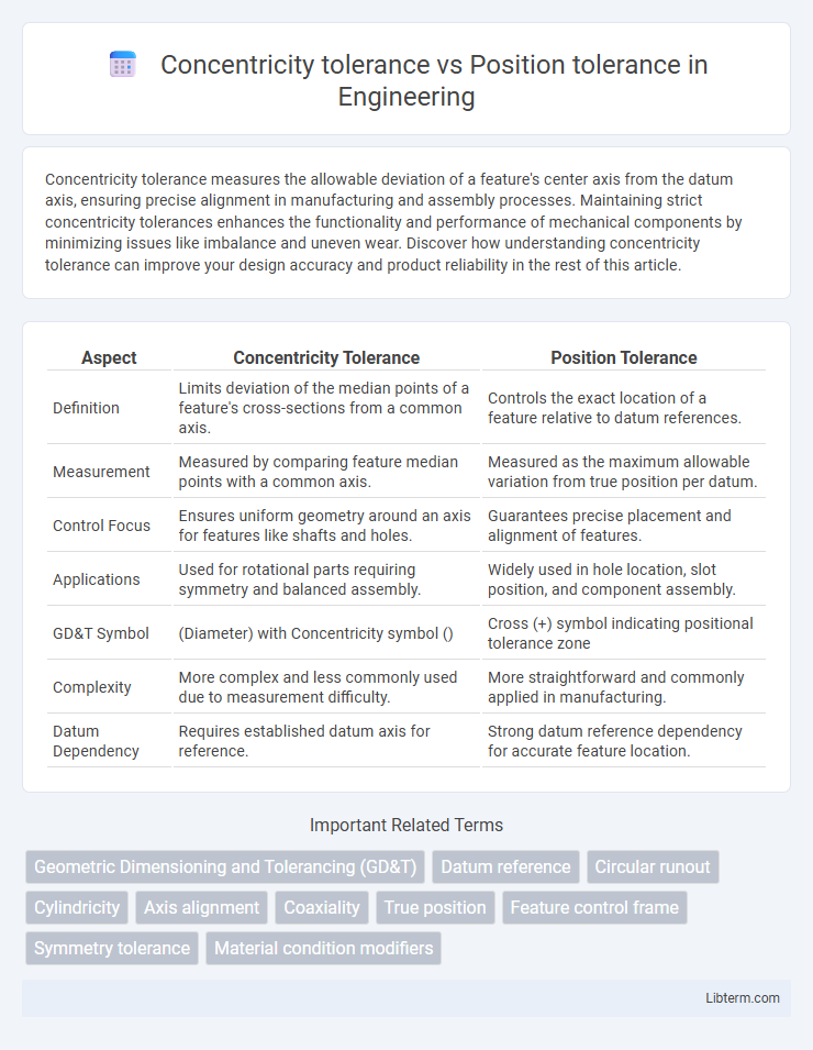
| Aspect | Concentricity Tolerance | Position Tolerance |
|---|---|---|
| Definition | Limits deviation of the median points of a feature's cross-sections from a common axis. | Controls the exact location of a feature relative to datum references. |
| Measurement | Measured by comparing feature median points with a common axis. | Measured as the maximum allowable variation from true position per datum. |
| Control Focus | Ensures uniform geometry around an axis for features like shafts and holes. | Guarantees precise placement and alignment of features. |
| Applications | Used for rotational parts requiring symmetry and balanced assembly. | Widely used in hole location, slot position, and component assembly. |
| GD&T Symbol | (Diameter) with Concentricity symbol () | Cross (+) symbol indicating positional tolerance zone |
| Complexity | More complex and less commonly used due to measurement difficulty. | More straightforward and commonly applied in manufacturing. |
| Datum Dependency | Requires established datum axis for reference. | Strong datum reference dependency for accurate feature location. |
Introduction to Geometric Dimensioning and Tolerancing (GD&T)
Concentricity tolerance in Geometric Dimensioning and Tolerancing (GD&T) controls the median points of diametrically opposed elements, ensuring they remain equidistant from a common axis, thus maintaining uniformity in circular features. Position tolerance regulates the permissible variation in the location, orientation, and sometimes the size of a feature, providing a more comprehensive control than concentricity by addressing the feature's exact placement relative to datums. Understanding these distinctions is crucial for precise manufacturing and assembly, as concentricity focuses strictly on axis alignment, while position tolerance accounts for broader spatial accuracy within defined geometric boundaries.
What is Concentricity Tolerance?
Concentricity tolerance specifies the allowable deviation of the median points of diametrically opposed elements from a common central axis, ensuring uniformity around a shared centerline. It is primarily concerned with the precise alignment of cylindrical or circular features in relation to a datum axis. Unlike position tolerance, which controls the exact location of features within a defined tolerance zone, concentricity tolerance measures the consistency of feature symmetry around that axis, critical for rotating parts to minimize imbalance.
What is Position Tolerance?
Position tolerance specifies the allowable deviation of a feature's axis, center, or location from its true position, ensuring precise alignment and assembly in mechanical parts. It controls the exact placement of holes, slots, or other features relative to a datum or reference frame, critical in complex assemblies. Unlike concentricity tolerance, which measures uniformity around a central axis, position tolerance directly governs the spatial accuracy and functional fit of components.
Key Differences: Concentricity vs Position
Concentricity tolerance controls the uniformity of the center axis of a feature relative to a datum axis, ensuring the median points of circular elements are colinear, which is crucial in rotational parts. Position tolerance defines the allowable deviation of a feature's axis or center from a theoretically exact location, providing precise control over feature placement in 3D space. Unlike concentricity, position tolerance offers greater flexibility and is easier to measure, making it preferred for complex geometric dimensioning and tolerancing (GD&T) applications.
How to Interpret Concentricity on Engineering Drawings
Concentricity tolerance on engineering drawings controls the median points of diametrically opposed elements to ensure they share a common axis within a specified tolerance zone, typically a cylindrical boundary. Position tolerance, on the other hand, governs the exact location of features relative to datums, often using a cylindrical or spherical tolerance zone for holes or pins. Interpreting concentricity requires understanding that it measures the deviation of central axes, not surface variation, ensuring symmetrical rotational alignment critical for parts like shafts and bearings.
How to Interpret Position Tolerance on Engineering Drawings
Position tolerance in engineering drawings specifies the allowable deviation of a feature's location from its true position, measured within a specified tolerance zone defined by datums. Interpreting position tolerance requires understanding the feature control frame, which includes the tolerance value, the datum references, and the type of geometric control applied. Unlike concentricity tolerance that controls the median points of diametrically opposed elements, position tolerance focuses on the feature's exact placement, ensuring proper fit and function in assembly.
Inspection Methods for Concentricity and Position
Concentricity tolerance inspection relies primarily on coordinate measuring machines (CMMs) or roundness measuring instruments to evaluate the coaxial alignment of multiple features relative to a common axis, ensuring uniform radial distance. Position tolerance is typically verified using CMMs or optical comparators that measure the exact location of a feature's center, axis, or center plane within a specified cylindrical tolerance zone. Both methods require precise probe paths and data analysis software to quantify deviations accurately, but position tolerance inspections emphasize location accuracy, whereas concentricity focuses on consistency of radial distance around a datum axis.
Applications of Concentricity and Position Tolerances
Concentricity tolerance is crucial in applications requiring precise alignment of cylindrical features, such as shafts and bearings, ensuring uniform rotation and reducing vibrations in mechanical assemblies. Position tolerance is widely applied in hole patterns, fastener placements, and component mounting to control the exact location of features relative to datums, enhancing assembly interchangeability and function. Both tolerances ensure quality and performance but are selected based on whether feature center alignment (concentricity) or spatial location accuracy (position) is critical to the design.
Common Mistakes and Misconceptions
Concentricity tolerance is often misunderstood as a simple measurement of surface alignment, while it actually requires precise evaluation of median points within the tolerance zones, making it more complex than position tolerance. Position tolerance is commonly mistaken for concentricity tolerance because both control location, but position tolerance controls the allowed deviation of feature axes or centers, offering a more practical and easier-to-inspect specification. A frequent error lies in applying concentricity tolerance where position tolerance is appropriate, leading to increased inspection difficulty, higher costs, and potential manufacturing delays.
Choosing the Right Tolerance for Your Design
Choosing the right tolerance between concentricity and position depends on the functional requirements of your design, as concentricity tolerance ensures uniformity of feature radii around a common axis while position tolerance controls the exact location of features within a specified tolerance zone. Concentricity is often critical in rotating parts where balance is paramount, whereas position tolerance is more suitable for assemblies requiring precise alignment of holes or slots. Evaluating the geometric importance and measurement practicality helps optimize manufacturing efficiency and part performance.
Concentricity tolerance Infographic