A bridge circuit is an electrical configuration used for measuring unknown resistance, capacitance, or inductance by balancing two legs of a circuit, often arranged in a diamond shape. Precise measurements depend on the accurate adjustment of known components until the bridge reaches equilibrium, indicated by zero voltage between two points. Discover how mastering bridge circuits can streamline your electronic diagnostics by exploring the detailed insights ahead.
Table of Comparison
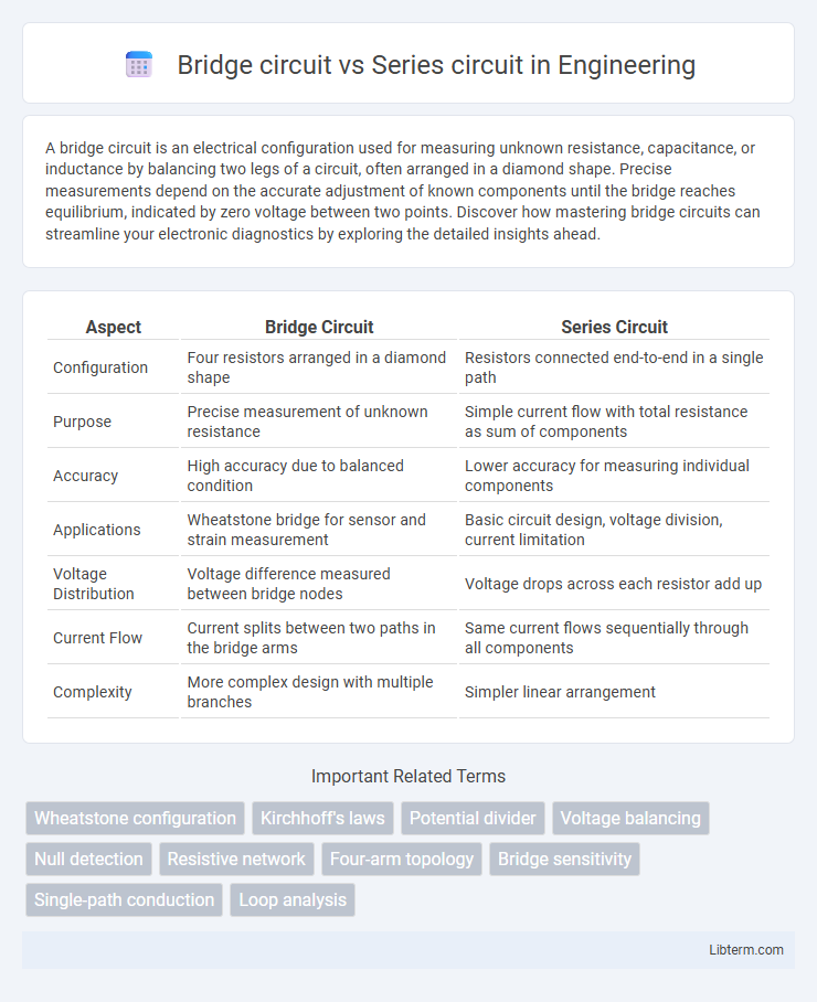
| Aspect | Bridge Circuit | Series Circuit |
|---|---|---|
| Configuration | Four resistors arranged in a diamond shape | Resistors connected end-to-end in a single path |
| Purpose | Precise measurement of unknown resistance | Simple current flow with total resistance as sum of components |
| Accuracy | High accuracy due to balanced condition | Lower accuracy for measuring individual components |
| Applications | Wheatstone bridge for sensor and strain measurement | Basic circuit design, voltage division, current limitation |
| Voltage Distribution | Voltage difference measured between bridge nodes | Voltage drops across each resistor add up |
| Current Flow | Current splits between two paths in the bridge arms | Same current flows sequentially through all components |
| Complexity | More complex design with multiple branches | Simpler linear arrangement |
Introduction to Bridge Circuits
Bridge circuits provide precise measurement of unknown electrical components by comparing two legs of a circuit, typically arranged in a diamond shape, unlike series circuits where components are connected end-to-end impacting total resistance. The Wheatstone bridge, a common bridge circuit, balances voltage across the bridge to determine unknown resistance with high accuracy. Bridge circuits enable sensitive detection of small changes in resistance, capacitance, or inductance, making them essential for sensor applications and calibration measurements.
Overview of Series Circuits
Series circuits consist of components connected end-to-end, forming a single path for current flow, causing the same current to pass through each element. Voltage divides across components according to their resistance, and the total resistance is the sum of individual resistances, impacting current magnitude. This configuration is fundamental in applications where current uniformity is required, but a single component failure interrupts the entire circuit.
Key Differences: Bridge vs Series Circuits
Bridge circuits utilize a configuration of four resistors arranged in a diamond shape, enabling precise measurement of unknown resistances through balancing conditions, whereas series circuits consist of components connected end-to-end, sharing the same current flow. The voltage distribution in bridge circuits varies across each resistor depending on the balance state, while series circuits have voltages that sum proportionally along the path. Bridge circuits are ideal for sensor applications requiring sensitivity and accuracy, while series circuits are simpler and commonly used for straightforward current control.
Principle of Operation: Bridge Circuits
Bridge circuits operate by comparing two voltage branches in a loop, balancing the circuit to achieve zero potential difference across the detector, which indicates equilibrium conditions. This principle allows precise measurement of unknown components such as resistors, capacitors, or inductors by adjusting known elements until the bridge is balanced. Unlike series circuits that rely on current flow through components, bridge circuits depend on voltage comparison to detect variations and achieve accurate calibration.
Working Mechanism: Series Circuits
Series circuits operate by connecting components end-to-end, forming a single path for current flow, ensuring the same current passes through each element. Voltage in a series circuit divides proportionally across the components based on their resistance, following Ohm's law. This configuration is ideal for applications requiring consistent current but varying voltage drops.
Applications of Bridge Circuits
Bridge circuits, such as the Wheatstone bridge, are widely used in precise measurement applications including strain gauges, temperature sensors, and impedance analysis, where balanced accuracy is crucial. Unlike series circuits, bridge circuits enable the detection of small changes in resistance or other electrical properties by comparing multiple circuit branches. This makes them essential in instrumentation systems for industrial monitoring, sensor calibration, and fault detection.
Applications of Series Circuits
Series circuits are widely used in applications requiring uniform current flow, such as in Christmas lights where bulbs are connected end-to-end to ensure the same current passes through each. These circuits are ideal for devices like voltage dividers, allowing control over voltage across components by varying resistance values. Series circuits also play a crucial role in fuse protection systems, where a break in the circuit interrupts current to prevent damage from overloads.
Advantages and Limitations of Bridge Circuits
Bridge circuits offer high accuracy in measuring unknown resistances, capacitances, and inductances by balancing two legs of a circuit, minimizing measurement errors compared to series circuits. They enable precise detection of small changes in resistance, making them ideal for sensor applications, though their complexity and sensitivity to component tolerances can limit practical implementation. Despite these limitations, bridge circuits provide stable and reliable measurements under varying environmental conditions, outperforming series circuits in precision tasks.
Pros and Cons of Series Circuits
Series circuits offer simple design and easy analysis due to their single path for current flow, making them cost-effective for basic applications. However, a major drawback is that a failure in any one component interrupts the entire circuit, leading to reduced reliability. Voltage drop across each component varies with resistance, which can limit their suitability for devices requiring consistent voltage.
Choosing Between Bridge and Series Circuits
Bridge circuits provide higher accuracy and sensitivity in measuring small changes in resistance and are ideal for applications requiring precise detection like strain gauges or temperature sensors. Series circuits, with their simpler configuration, offer straightforward current flow control and are suitable for basic applications where individual component voltage drops matter less. Choosing between these depends on the need for precision measurement versus simplicity and cost-effectiveness in circuit design.
Bridge circuit Infographic