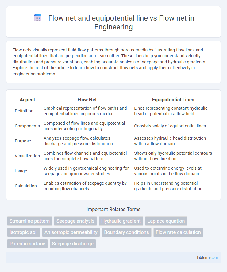
Flow nets visually represent fluid flow patterns through porous media by illustrating flow lines and equipotential lines that are perpendicular to each other. These lines help you understand velocity distribution and pressure variations, enabling accurate analysis of seepage and hydraulic gradients. Explore the rest of the article to learn how to construct flow nets and apply them effectively in engineering problems.
Table of Comparison
| Aspect | Flow Net | Equipotential Lines |
|---|---|---|
| Definition | Graphical representation of flow paths and equipotential lines in porous media | Lines representing constant hydraulic head or potential in a flow field |
| Components | Composed of flow lines and equipotential lines intersecting orthogonally | Consists solely of equipotential lines |
| Purpose | Analyzes seepage flow, calculates discharge and pressure distribution | Assesses hydraulic head distribution within a flow domain |
| Visualization | Combines flow channels and equipotential lines for complete flow pattern | Shows only hydraulic potential contours without flow direction |
| Usage | Widely used in geotechnical engineering for seepage and groundwater studies | Used to determine energy levels at various points in the flow domain |
| Calculation | Enables estimation of seepage quantity by counting flow channels | Helps in understanding potential gradients and pressure distribution |
Introduction to Flow Nets
Flow nets visually represent groundwater flow through porous media by depicting flow lines and equipotential lines, forming a network of curvilinear squares. Flow lines indicate the flow direction of water particles, while equipotential lines represent locations of equal hydraulic head, perpendicular to flow lines. This graphical method aids in analyzing seepage patterns, flow velocity, and hydraulic gradients in soil mechanics and hydrogeology.
Principles of Flow Net Construction
Flow nets consist of flow lines and equipotential lines intersecting orthogonally, representing steady-state seepage through porous media. The construction principles include drawing flow lines to follow the direction of seepage velocity and equipotential lines perpendicular to flow lines, ensuring equal spacing between adjacent lines to represent uniform potential drops and flow rates. Accurate flow net construction facilitates visualization of flow patterns and calculation of hydraulic parameters such as seepage quantity and pressure distribution.
Components of a Flow Net
Flow nets consist of flow lines and equipotential lines that intersect orthogonally, representing the directions of fluid flow and constant potential respectively. Key components of a flow net include flow channels, flow lines, equipotential lines, and flow nets themselves, which are used to analyze seepage and hydraulic gradients in porous media. The precise spacing and shape of these components aid in calculating seepage quantities and identifying potential flow paths accurately.
Understanding Equipotential Lines
Equipotential lines in a flow net represent locations where the hydraulic head is constant, indicating no change in potential energy within the fluid at these points. These lines intersect flow lines at right angles, forming a grid that helps visualize fluid movement through porous media by separating zones of equal potential. Understanding equipotential lines enhances the ability to analyze pressure distribution and hydraulic gradients in groundwater flow and seepage studies.
Flow Lines vs Equipotential Lines
Flow lines represent the actual paths followed by fluid particles in a flow field, indicating the direction of fluid movement, while equipotential lines are perpendicular to flow lines and represent lines of constant hydraulic head or potential. Flow lines never intersect each other, and equipotential lines also do not intersect, maintaining orthogonality to flow lines throughout the flow net. The flow net, composed of flow lines and equipotential lines, provides a graphical representation of velocity distribution and potential gradients, essential for analyzing seepage and fluid flow in porous media.
Flow Net vs Equipotential Line: Key Differences
Flow nets visualize fluid flow patterns through porous media using perpendicular flow lines and equipotential lines representing constant hydraulic head. Flow nets illustrate the overall flow distribution and velocity vectors, while equipotential lines specifically indicate locations of equal potential energy without showing flow direction. Understanding the distinction aids in analyzing seepage problems, pressure distribution, and hydraulic gradients in geotechnical and groundwater engineering.
Applications of Flow Nets in Engineering
Flow nets are graphical tools used in civil and geotechnical engineering to analyze groundwater flow through soils, visualize seepage patterns, and estimate hydraulic gradients. Equipotential lines within flow nets represent locations of equal hydraulic head, helping engineers identify critical zones of seepage pressure and potential failure in earth dams, retaining walls, and levees. Applications of flow nets include designing drainage systems, evaluating soil permeability, and assessing seepage under hydraulic structures to ensure stability and prevent erosion or piping.
Importance of Equipotential Lines in Flow Analysis
Equipotential lines in a flow net represent locations where the hydraulic head remains constant, enabling precise visualization of energy distribution within a porous medium. These lines are crucial for calculating seepage quantities and understanding pressure gradients, which inform soil stability and seepage control measures. Integrating equipotential lines with flow nets enhances the accuracy of groundwater flow analysis and supports effective engineering design in geotechnical applications.
Flow Net Interpretation and Analysis
Flow nets graphically represent groundwater flow through porous media by using a grid of flow lines and equipotential lines that intersect orthogonally, allowing visualization of flow patterns and hydraulic gradients. Equipotential lines connect points of equal hydraulic head, while flow lines indicate the path water particles follow, enabling calculation of seepage quantities and pressure distributions. Accurate flow net interpretation supports critical geotechnical analyses such as seepage rate estimation, uplift pressure assessment, and slope stability evaluation.
Conclusion: Choosing Flow Nets or Equipotential Lines
Flow nets provide a comprehensive visualization of fluid flow patterns by combining flow lines and equipotential lines, making them essential for analyzing seepage and groundwater flow problems. Equipotential lines alone represent points of equal hydraulic head but lack the directional flow information that flow nets deliver, limiting their usability in complex flow scenarios. Choosing between flow nets and equipotential lines depends on the need for detailed flow direction and velocity analysis, with flow nets being the preferred tool for complete hydraulic assessments.
Flow net and equipotential line Infographic